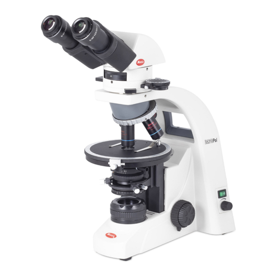
Motic BA310 Pol Instruction Manual
Polarizing microscope
Hide thumbs
Also See for BA310 Pol:
- Instruction manual (20 pages) ,
- Instruction manual (17 pages) ,
- Instructions manual (30 pages)

Related Manuals for Motic BA310 Pol


Summary of Contents for Motic BA310 Pol
- Page 1 BA310 Pol Polarizing Microscope Instructions Manual WWW.MOTIC.COM MOTIC INCORPORATION LTD.
- Page 2 Therefore, all descriptions and illustrations in this instruction manual, including all specifications are subject to change without notice. Although every effort has been made to ensure the accuracy of this instruction manual, if you note any points that are unclear or inaccurate, please contact Motic agency or our Technical Service directly.
- Page 3 Introduction Polarizing microscopes are used in the study of thin sections of minerals and rocks as well as other anisotropic materials (fibers, plastics, etc.). The optical system is similar to that of modern compound microscopes. The most distinctive features of a polarizing microscope are the rotatable stage, polarizer and analyzer, Bertrand lens system as well as mica plate, gypsum plate and quartz wedge.
-
Page 4: Table Of Contents
Table of contents 1. Nomenclature 2. Setting Up The Instrument 3. Assembling the microscope Verifying input voltage Halogen lamp Specimen clip Attachable mechanical stage (optional) Objectives Condenser Intermediate tube Analyser slider Compensators 3.10 Eyepiece tube 3.11 Eyepieces 3.12 Filters 3.13 Power cord 3.14 Epi-illuminator 4. - Page 5 4.12 Compensators A. 1/4λ-plate B. 1λ-plate C. Quartz Wedge 4.13 Centering the Objectives 4.14 Epi-illuminator 5. Photomicrographic procedure 6. Terminology 7. Troubleshooting table 8. Care and maintenance 9. Warning labels...
-
Page 6: Nomenclature
1 . Nomenclature BA310 EPI-Pol... - Page 7 BA310 EPI-Pol...
-
Page 9: Setting Up The Instrument
2. Setting up the Instrument Avoid placing the instrument in locations exposed to direct sunlight, dust, vibration, high temperature, high humidity and where it is difficult to unplug the power supply cord. Operating environment Indoor use Altitude: Max 2000 meters ... -
Page 10: Assembling The Microscope
3. Assembling the microscope 3.1 Verifying input voltage The automatic voltage selection works with a broad range of settings. However, always use a power cord that is rated for the voltage used in your area and that has been approved to meet local safety standards. -
Page 11: Halogen Lamp
3.2 Halogen lamp Tungsten-halogen lamps operate at very high temperatures and may cause serious burn injuries if handled while hot. When replacing these lamps, always allow them to cool down before removing them from the lamp socket. Avoid handing the bulb directly because fingerprints will be burned into the glass, often initiating premature lamp failure. -
Page 12: Intermediate Tube
3.7 Intermediate tube To mount the intermediate tube, start loosening the intermediate tube clamp screw on the microscope arm. Insert the intermediate tube into the round dovetail mount on the microscope arm. The orientation pin on the lower side of the intermediate tube has to fit to the receiving groove on the microscope arm. -
Page 13: Filters
3.12 Filters • Place the chosen filter in the filter holder located above the field lens by removing the filter holder ring. Avoid polluting filter and lens surfaces with dust, dirt or finger prints. Filter options: Filter Function ND2 (Transmission=50%) ND4 (T=25%) For brightness adjustment in photomicrography ND16 (T=6.25%) -
Page 14: Microscopy
4. Microscopy Manipulation of each component 4.1 Coarse and fine focusing • Focusing is carried out with the coarse and fine focus knobs at the left and right side of the microscope stand. • The direction of vertical movement of the stage corresponds to the turning direction of the focus knobs. -
Page 15: Stage Upper Limit Stop Adjustment
4.2 Stage upper limit stop adjustment: (The upper Stage Limit is preset at the factory; please only adjust if necessary) • The Stage Upper Limit stop marks the uppermost stage position. This is to prevent damage of the objectives while focussing. If the correct preset has been changed accidently during transport, please perform the following procedure: - Loosen the Stage upper Limit Stop. -
Page 16: Diopter Adjustment
4.5 Diopter adjustment • Every human eye is different, so only the adjustment of the eyepieces will bring the microscope to its best performance. • Set the diopter on both eyepieces to the “0” position. • Change to 10x magnification and focus the image of the specimen with one eye only. •... -
Page 17: Use Of Aperture Diaphragm
4.7 Use of aperture diaphragm • The condenser aperture diaphragm is provided for adjusting the numerical aperture (N.A.) of the illumination system of the microscope. It determines the resolution of the image, contrast, depth of focus and brightness. • Stopping down will lower the resolution and brightness but increase the contrast and depth of focus. •... -
Page 18: Brightness And Contrast Adjustment
4.9 Brightness and contrast adjustment • Neutral density filters are used for brightness adjustment in routine microscopy and photomicrography without affecting the colour temperature. • The Green interference filter (546nm) is used in combination with the quartz wedge. 4.10 Orientation of polarizer and analyzer •... -
Page 19: Focusing And Centering The Bertrand Lens
4.11 Focusing and centering the Bertrand lens • Rotate the Bertrand lens turret to “B” position and bring the Bertrand lens in the optical path. • Bring 40x Objective into optical path. • Use the Bertrand lens focus ring under the Bertrand lens turret to focus on the image of the condenser aperture diaphragm that is stopped down to 70 –... -
Page 20: Plate
B. 1λ-plate (sensitive tint or first-order red) - The 1λ-plate is a gypsum plate of a thickness to give1λ optical path difference for green light of 550 nm. This wavelength is therefore extinguished with the resulting interference colour having the typical tint of the first-order red/violet. This magenta colour is sometimes named ‘sensitive tint’. -
Page 21: Centering The Objectives
4.13 Centering the objective • The BA310 Polarizing microscope allows for centering of three objectives in relation to a reference objective. • Before centering the objectives, look through the binocular tube at the field of view, pick out an easily recognizable target and move the target in the middle to the cross line by moving the sample. -
Page 22: Photomicrographic Procedure
5. Photomicrographic Procedure • To ensure vibration free operation, set the microscope on a sturdy vibration free table or a bench with a vibration proof device. • Pull the beam split lever of the trinocular eyepiece tube all the way out to the limit, the ratio of light entering the phototube will be 100% •... -
Page 23: Terminology
6. Terminology Aperture, Numerical (N.A.) Diaphragm, Condenser The numerical aperture is an important factor A diaphragm, which controls the effective size of determining the resolution power of the the condenser opening angle and thus the condenser and objective. It is calculated by the illumination aperture. - Page 24 Conoscopic Observation Orthoscopic Observation The study of the back focal plane of the objective This is the normal way of viewing an object is called conoscopic as the observations are through a microscope. With Koehler illumination, associated with the cone of light furnished by the the image of the field diaphragm is projected by condenser and viewed by the objective.
-
Page 25: Troubleshooting Table
7. Troubleshooting Table As you use your microscope, you may occasionally experience a problem. The troubleshooting table below contains the majority of frequently encountered problems and the possible causes. Problem Possible Cause Analyser slider in intermediate position Compensator slider in midway position Bertrand lens in optical path Condenser not mounted correctly Condenser is not centered... - Page 26 Lamp voltage is set too low Image tinged yellow Blue filter is not in Focusing is not possible with high Slide is upside down magnification objectives Cover glass is too thick High magnification objectives strike the Slide is upside down specimen when changing over from low to Cover glass is too thick high magnification...
-
Page 27: Care And Maintenance
• Proper handling of the microscope will ensure years of trouble free service. • If repair become necessary, please contact your Motic agency or our Technical Service direct. Note: • If equipment is used in a manner not specified by the manufacturer, the protection provided by the equipment may be impaired. - Page 28 E. Bulb replacement The bulb and the lamphouse become very hot during and after a period of operation. Risk of burn – Do not touch the bulb during or immediately after period of operation. Make sure the bulb has cooled sufficiently before attempting to replace the bulb. •...
-
Page 29: Warning Labels
Make sure the lamp has cooled sufficiently before attempting to replace the lamp. Don’t pick up from the bottom during equipment operation. Proper handling of the microscope will ensure years of trouble free service. If repair become necessary, please contact your Motic agency or our Technical Service directly. - Page 30 Fax: 86-0592-562 7855 © 2007-2008 Motic China Group Co., Ltd. All rights reserved. Motic is a registered trademark and service mark of Motic China Group Co., Ltd. Microsoft Windows logo is a registered trademark of Microsoft Corporation. All other trademarks are the property of their respective owners.
Need help?
Do you have a question about the BA310 Pol and is the answer not in the manual?
Questions and answers