Table of Contents
Advertisement
Advertisement
Table of Contents

Related Manuals for Motic BA410 Series


Summary of Contents for Motic BA410 Series
- Page 2 We are constantly endeavouring to improve our instruments and to adapt them to the requirements of modern research techniques and testing methods. This involves modification to the mechanical structure and optical design of our instruments. Therefore, all descriptions and illustrations in this instruction manual, including all specifications are subject to change without notice.
- Page 3 INFINITY CORRECTED OPTICS In this optical concept the light beams are parallel after leaving the objective in the direction of the eyepieces. A second optical element, the tube lens (normally located in the eyepiece tube) is used to converge the parallel beams, resulting in an intermediate image.
-
Page 4: Table Of Contents
TABLE OF CONTENTS Section Nomenclature Setting up the instrument Operating environment Assembling the microscope Verifying Input voltage 1 Mechanical stage 2 Specimen holder 3 Objectives 4 Condenser 5 Eyepiece tube 6 Eyepieces 7 Illumination 8 Filters 9 Power cord IV Microscopy 1 Coarse and fine focusing 2 Coarse focus torque adjustment 3 Coarse focus quick stop... -
Page 5: Section I Nomenclature
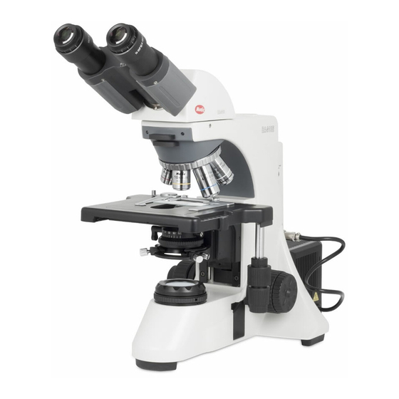
I. Nomenclature MOTIC BA410 (30W Halogen) - Page 6 MOTIC BA410 (Trinocular) 30W Halogen...
- Page 7 MOTIC BA410 30W Halogen...
-
Page 8: Setting Up The Instrument
II. Setting up the instrument Avoid placing the instrument in locations exposed to direct sunlight, dust, vibration, high temperature, high humidity and where it is difficult to unplug the power supply cord. Operating environment Indoor use Altitude: Max 2000 meters Ambient temperature: 15°C to 35°C Maximum relative humidity: 75% for temperature up to 31ºC decreasing linearly to 50% relative humidity at 40ºC... -
Page 9: Mechanical Stage
Electrical Specifications: 30W Halogen Bulb Input: 90-240V~, 80VA, 50-60Hz Bulb: 6V 30W Halogen Fuse: 250V T2.5A (If the original fuse is blown, please replace with specified fuse) 1. Mechanical stage Loosen the stage clamp screw; fit the stage into the circular dovetail mount. An orientation notch at the back of the stage has to fit to an orientation pin at the stage carrier. -
Page 10: Condenser
4. Condenser Raise the stage by turning the coarse focus knob. Completely lower the condenser carrier by turning the condenser focus knob. Insert the condenser into the dovetail mount with aperture scale facing forward towards the user. Secure it with the condenser clamp screw. Turn the condenser focus knob to raise the condenser as far as it will go. -
Page 11: Eyepieces
6. Eyepieces Use the same magnification eyepieces for both the eyes. Inserting or removing the eyepieces is facilitated by twisting the eyepieces when pushing in or pulling out. 7. Illumination The quartz halogen bulb, used as a light source, has higher luminance and color temperature than conventional tungsten bulb. -
Page 12: Filters
8. Filters Remove the collector cover and place the filter in the filter holder located around the field lens, screw the collector cover, taking care that dust, dirt and fingerprints do not get on the filter and the field lens. 1. -
Page 13: Power Cord
9. Power cord Connect the socket of the of the power cord to the AC inlet on the rear of the base of the microscope. Plug in the other end of the cord to an AC outlet with ground conductor. IV. -
Page 14: Coarse Focus Quick Stop
3. Coarse Focus Quick Stop The coarse focus height stop serves as a quick accessible possibility for the user to limit the upper focus position in order to prevent a collision of the Objective with the specimen. Focus on the specimen using the lowest power objective and the coarse focus knob. Rotate the highest power objective into place. -
Page 15: Beam Splitter Lever
1. Stage Upper Limit Stop 5. Beam Splitter Lever When the slider is pushed in, 100% of the light will enter the eyepieces. When pulled out, the light beam will be divided as follows: 20:80 (visual: photo; standard tube) 0:100 (visual: photo; tube for low light situations, optional tube) The triple position tube (optional) is the most flexible tube by giving 2 photo positions: 20:80 (visual: photo;... -
Page 16: Interpupillary Distance Adjustment
6. Interpupillary distance adjustment Before adjusting the interpupillary distance, bring a specimen into focus using the 10x objective. Adjust the interpupillary distance so that both the right and left field of view become one. This adjustment will enable the user to observe the specimen with both eyes Eyepiece tubes can be swivelled up or down to adjust the viewing height to suit individual preference of comfort viewing. -
Page 17: Diopter Adjustment
7. Diopter adjustment Every human eye is different, to adjust the Instrument to best performance adjustment can be necessary. Set the diopter on both eyepieces to the “0” position. Change to 10x Magnification and focus the image of the specimen with one eye only. Use the Eye which is most convenient for first focussing. -
Page 18: Use Of Aperture Diaphragm
1. Condenser Centering Screws 9. Use of aperture diaphragm The condenser aperture diaphragm is provided for adjusting the numerical aperture (N.A.) of the illuminating system of the microscope, it decides the resolution of the image, contrast, depth of focus and brightness. Stopping down will lower the resolution and brightness but increase the contrast and depth of focus. -
Page 19: Use Of Field Diaphragm
10. Use of field diaphragm The field diaphragm determines the illuminated area on the specimen. For normal observation, the diaphragm is set slightly larger than the field of view. If the illuminated area is set much larger than the field of view extraneous light will enter the field of view. -
Page 20: Photomicrographic Procedure
V. Photomicrographic procedure To ensure vibration free operation, set the microscope on a sturdy vibration free table or a bench with a vibration proof device. Pull the optical path selection lever of the trinocular eyepiece tube all of the way out to the limit. -
Page 21: Using Oil Immersion Objectives
Oil immersion objectives are labelled with the additional engraving “Oil” and are to be immersed in oil between the specimen and the front of the objective. The immersion oil supplied by Motic is synthetic, non-fluorescing and non-resining oil, with a refractive index of 1.515 Normally, cover glass must be used with oil immersion objectives with a few exceptions. -
Page 22: Troubleshooting Table
VII. Troubleshooting Table As you use your microscope, you may occasionally experience a problem. The troubleshooting table below contains the majority of frequently encountered problems and the possible causes. Problem Possible Cause Bulb not installed properly Condenser not mounted correctly Condenser is not centred Condenser is set too low Condenser top lens not fully swung in/out... - Page 23 Dried stain or oil on objective lens. Lens must Poor image (low contrast or be removed from the microscope and resolution) examined with a magnifier (an inverted eyepiece can be used) to check for dirt Stage installed on inclined plane Specimen holder not fixed securely on stage Specimen not secured in position Uneven focus...
-
Page 24: Care And Maintenance
2. Never attempt to dismantle any parts other than described in this manual. If you notice any malfunction, contact your nearest Motic representative. B. Cleaning the Microscope 1. - Page 25 Store the objectives, eyepieces and filters in a container or desiccator with drying agent. Proper handling of the microscope will ensure years of trouble free service. If repair becomes necessary, please contact your Motic agency or our Technical Service direct. Note: If equipment is used in a manner not specified by the manufacturer, the warranty may be void.
- Page 26 Close the cover and secure with it with lamp housing cover clamp screw.
-
Page 27: Warning Label
Make sure the bulb has cooled sufficiently before attempting to replace the bulb. Don’t pick the microscope up from the bottom during equipment operation. Proper handling of the microscope will ensure years of trouble free service. If repair become necessary, please contact your Motic agency or our Technical Service directly. - Page 28 Fax: 86-0592-562 7855 2007-2008 Motic China Group Co., Ltd. All rights reserved. Motic is a registered trademark and service mark of Motic China Group Co., Ltd. Microsoft Windows logo is a registered trademark of Microsoft Corporation. All other trademarks are the property of their respective owners.
Need help?
Do you have a question about the BA410 Series and is the answer not in the manual?
Questions and answers