Sign In
Upload
Download
Table of Contents
Contents
Add to my manuals
Delete from my manuals
Share
URL of this page:
HTML Link:
Bookmark this page
Add
Manual will be automatically added to "My Manuals"
Print this page
×
Bookmark added
×
Added to my manuals
Manuals
Brands
AEMC Manuals
Measuring Instruments
3710
User manual
AEMC 3710 User Manual
Clamp-on ground resistance testers
Hide thumbs
1
2
3
Table Of Contents
4
5
6
7
8
9
10
11
12
13
14
15
16
17
18
19
20
21
22
23
24
25
26
27
28
29
30
31
32
33
34
35
36
37
38
39
40
page
of
40
Go
/
40
Contents
Table of Contents
Troubleshooting
Bookmarks
Table of Contents
Table of Contents
Warning
Receiving Your Shipment
Packaging
Government Orders
Description
Electrical Specifications
Mechanical Specifications
Safety Specifications
Model 3710 Controls
Model 3730 Controls
Digital Display Features
Additional Features of the Model 3730
Function Controls
Programming the Alarm Setpoint
Changing the Alarm Trigger
Memory
Memory Recall
Clear Memory
Function Access Summary
Programming Summary
Principle of Operation
Field Applications
Operating Reference Card
Calibration Check Loop
Commonly Asked Questions
Battery Replacement
Troubleshooting
Repair and Calibration
Advertisement
Quick Links
1
Electrical Specifications
2
Model 3710 Controls
3
Calibration Check Loop
4
Repair and Calibration
Download this manual
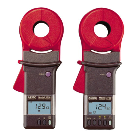
Clamp-On
Ground Resistance Testers
Models 3710 and 3730
USER MANUAL
Chauvin Arnoux, Inc. d.b.a. AEMC
®
Instruments
99-MAN-100061 Rev 05 03/98
Table of
Contents
Previous
Page
Next
Page
1
2
3
4
5
Advertisement
Table of Contents
Need help?
Do you have a question about the 3710 and is the answer not in the manual?
Ask a question
Questions and answers
Related Manuals for AEMC 3710
Measuring Instruments AEMC 3731 User Manual
Clamp-on ground resistence tester (40 pages)
Measuring Instruments AEMC 3711 User Manual
Clamp-on ground resistence tester (40 pages)
Measuring Instruments AEMC 3730 User Manual
Clamp-on ground resistance testers (40 pages)
Measuring Instruments AEMC powerpad 3945 Manual
Three-phase power quality analyzer (5 pages)
Measuring Instruments AEMC PowerPad 3945 User Manual
3-phase power quality analyzer (89 pages)
Measuring Instruments AEMC PowerPad 3945-B User Manual
3-phase power quality analyzer (108 pages)
Measuring Instruments AEMC 300-24-2-10 User Manual
Ampflex flexible ac current probes (22 pages)
Measuring Instruments AEMC AmpFlex 300A User Manual
Flexible ac current probes (24 pages)
Measuring Instruments AEMC 3910 User Manual
True rms power meter (24 pages)
Measuring Instruments AEMC 403 User Manual
Clamp-on meter (44 pages)
Measuring Instruments AEMC 205 User Manual
Power clamp-on meter (52 pages)
Measuring Instruments AEMC 5070 User Manual
Megohmmeter (96 pages)
Measuring Instruments AEMC SIMPLE LOGGER II User Manual
Trms voltage (28 pages)
Measuring Instruments AEMC 6536 User Manual
Megohmmeter (48 pages)
Measuring Instruments AEMC SL261 User Manual
Ac/dc current oscilloscope probe (20 pages)
Measuring Instruments AEMC 6240 User Manual
Micro-ohmmeter (44 pages)
This manual is also suitable for:
3730
Table of Contents
Print
Rename the bookmark
Delete bookmark?
Delete from my manuals?
Login
Sign In
OR
Sign in with Facebook
Sign in with Google
Upload manual
Upload from disk
Upload from URL


Need help?
Do you have a question about the 3710 and is the answer not in the manual?
Questions and answers