Table of Contents
Advertisement
Quick Links
Advertisement
Table of Contents

Related Manuals for AEMC 1015


Summary of Contents for AEMC 1015
- Page 1 1015 MEGOHMMETER E N G L I S H User Manual...
- Page 3 The recommended calibration interval for this instrument is 12 months and begins on the date of receipt by the customer. For recalibration, please use our calibration services. Refer to our repair and calibration section at www.aemc.com. Serial #: ________________________________ Catalog #: 1403.01 Model #:...
-
Page 4: Table Of Contents
Table of Contents 1. INTRODUCTION ................3 1.1 International Electrical Symbols ..........3 1.2 Definition of Measurement Categories ........4 1.3 Receiving Your Shipment ............4 1.4 Ordering Information ..............4 1.4.1 Accessories and Replacement Parts ......4 2. PRODUCT FEATURES ..............5 2.1 Description ................5 2.2 Features ..................5 2.3 Control Features ...............6 3. SPECIFICATIONS................7 3.1 Electrical Specifications ............7 3.2 General Specifications ..............8 3.3 Safety Specifications ..............8... -
Page 5: Introduction
• These megohmmeters are sources of high voltage, as is the sample connected to them. All persons performing or assisting in the tests must follow all safety precautions to prevent electrical shock to themselves and to others. • AEMC considers the use of rubber gloves to be an excellent safety practice even if the equipment is properly operated and correctly grounded. • When testing capacitance samples, make sure that they have been properly discharged and that they are safe to touch. Dielectric insula-... -
Page 6: Definition Of Measurement Categories
(inside megohmmeter), four 1.5V alkaline “AA” batteries (not installed), and a user manual. 1.4.1 Accessories and Replacement Parts Set of replacement leads ............. Cat. #2119.01 Carrying Case..............Cat. #2119.02 Fuses, set of 5, 1.6A ............Cat. #2970.22 Order Accessories and Replacement Parts Directly Online Check our Storefront at www.aemc.com for availability Megohmmeter Model 1015... -
Page 7: Product Features
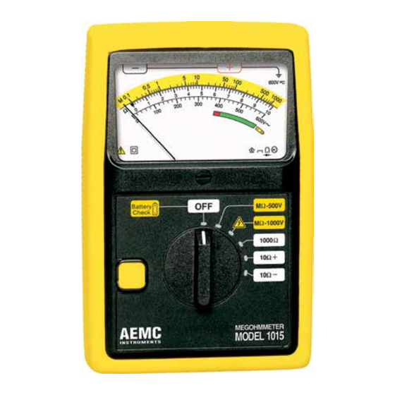
A built-in battery tester is provided by simply pressing the yellow push button when the selector switch is in the OFF position. Voltmeter (safety check) with a range of 0 to 600V is standard and works when the selector switch is in the 500V position or the 1000V position. Features • Measures insulation at 1000V • 0 to 1000Ω resistance range • Push button for battery check • Designed for harsh environments: offshore, mining, heavy-duty field, industrial, commercial electrical and military use • 0 to 10Ω+ and 0 to 10Ω- continuity ranges • Continuity 200mA test current • Small and lightweight • Large, direct-reading, colored scale • 600V test voltage range (safety check) • Yellow non-slip shockproof case Megohmmeter Model 1015... -
Page 8: Control Features
Control Features – Figure 2 1. Line (–) terminal 2. Earth/Ground (+) terminal 3. Mechanical zero adjustment screws 4. 4-position rotary switch 5. Protective rubber housing 6. Push-to-test button 7. Battery check and indication display Megohmmeter Model 1015... -
Page 9: Specifications
Short Circuit Current: ≥ 200 mA Open Circuit Voltage: 4.5 to 6.5V Accuracy: ±3% full scale RESISTANCE TESTS Range: 0 to 1000Ω Short Circuit Current: ≥ 2 mA Open Circuit Voltage: 4.5 to 6.5V Accuracy: ±3% full scale VOLTAGE TESTS (Safety Check) Voltage Range: 0 to 600V Frequency: 45 to 400Hz Accuracy: 3% of full scale Input Impedance: 300kΩ Megohmmeter Model 1015... -
Page 10: General Specifications
IEC 801: Electromagnetic compatibility for measurement and control equipment in industrial processes Part 2: Sections relating to electrostatic discharges Part 3: Sections relating to radiated electric fields Part 4: Sections relating to electrostatic discharges Part 5: Sections relating to electric shocks IEC 68.2.6: Vibrations IEC 68.2.27: Shocks IEC 68.2.29: Shakes IEC 68.2.31: Bumps IEC 68.2.32: Free fall UL 94: Self-extinguishing capability Specifications are subject to change at any time without notice Megohmmeter Model 1015... -
Page 11: Operation
NOTE: If measuring voltage on a DC circuit, the pointer will deflect but the measurement may be inaccurate. Insulation Resistance Testing (MΩ Range) After checking for a live circuit (see Safety Check above), connect the megohmmeter. Several connection examples are illustrated in Figures 3 through 10. 4.2.1 Test Voltage No published standard tells which voltage to choose for any given winding. However, published recommendations could be summarized as follows: Rated Voltage of Motor Test Voltage Below 115 250V 250V or 500V 500V 500V or 1000V Megohmmeter Model 1015... -
Page 12: Spot Testing
It is not unusual for a winding to be 10 to 100 times the recommended minimum value (IEEE Std. #43-1974: Recommended Practice for Testing Insulation Resistance of Rotating Machinery), but this varies with tem- perature and humidity. 4.2.3 Ratio Testing In time resistance reading (Dielectric Absorption Ratio), readings are taken at 30 and 60 seconds to obtain the dielectric absorption ratio. Insulation resistance @ 60s = Dielectric Absorption Ratio (DAR) Insulation resistance @ 30s This test is useful to increase the accuracy of spot testing. In general, a ratio of 1.25:2 or better should be required. A ratio below this indicates that repair is probably needed. Remember, a DC insulation test may be used for acceptance testing, but is more commonly used to check the gradual deterioration of equipment over its life. Consult your equipment manufacturer for specific test or test voltage if not known. Insulation resistance decreases with moisture, temperature and age and should be recorded over time at a given temperature and corrected. Megohmmeter Model 1015... -
Page 13: Tips For Successful Insulation Resistance Testing
Cable Insulation 600V Battery MΩ - 500 V Check MΩ - 1000 V 1000 Ω 10 Ω + 10 Ω − MEGOHMMETER AEMC MODEL 1015 I N S T R U M E N T S Figure 3 Megohmmeter Model 1015... - Page 14 Cable Insulation 600V Battery MΩ - 500 V Check MΩ - 1000 V 1000 Ω 10 Ω + 10 Ω − MEGOHMMETER AEMC MODEL 1015 I N S T R U M E N T S Figure 5 Megohmmeter Model 1015...
- Page 15 1000 Ω time. 10 Ω + 10 Ω − By removing the jumpers, readings MEGOHMMETER AEMC MODEL 1015 I N S T R U M E N T S can be made between the individual conductors and ground. Figure 7 Megohmmeter Model 1015...
-
Page 16: Insulation Resistance Measurements On Motors
1000 Ω 10 Ω + 10 Ω − tance value can now be MEGOHMMETER AEMC MODEL 1015 determined. I N S T R U M E N T S Figure 9 Read between phases “A” and “B”, then “B” and “C”, then “C” and “A”. Megohmmeter Model 1015... -
Page 17: Continuity
VDE 0413-4. If your work does not require you to conform to this standard, only one measurement is necessary. • Return to “OFF” after use. NOTE: For better measurement accuracy on the 10Ω+ and the 10Ω– ranges, measure the resistance of the leads by short-circuit- ing them, then subtract this value from the measured values. Resistance Measurements • Set the switch to the 1000Ω position. The measurement is done auto- matically; you do not need to press the yellow button. • Read the value on the white scale 0 to 10Ω, then multiply the reading by 100 to get the actual value measured. • Return to “OFF” after use. Megohmmeter Model 1015... -
Page 18: Maintenance
• 200 insulation measurements of 10 seconds on the MΩ -1000V range for R = 1MΩ. • 1500 continuity measurements of 10 seconds on the 10Ω RED zone or below: GREEN zone: Battery needs to be replaced Battery is good range. NOTE: The instrument will operate correctly with a battery voltage range of 4.5 to 6.5V. Megohmmeter Model 1015... -
Page 19: Battery And Fuse Replacement
• To close the back stand flush with the back cover, apply light pressure at Point A in Fig. 11. Cover screws 1.6 A fuse Point A 1.5 V batteries LR6 Figure 11 5.1.3 Cleaning • Clean the body of the instrument with a cloth lightly moistened with soapy water. • Wipe clean with a cloth moistened with clean water and dry. • Do not use solvent. Megohmmeter Model 1015... -
Page 20: Repair And Calibration
NOTE: You must obtain a CSA# before returning any instrument. Technical and Sales Assistance If you are experiencing any technical problems, or require any assistance with the proper operation or application of your instrument, please call, mail, fax or e-mail our technical support team: Chauvin Arnoux , Inc. d.b.a. AEMC Instruments ® ® 200 Foxborough Boulevard Foxborough, MA 02035 USA Phone: (800) 343-1391 (508) 698-2115 Fax: (508) 698-2118 E-mail: techsupport@aemc.com www.aemc.com NOTE: Do not ship Instruments to our Foxborough, MA address. Megohmmeter Model 1015... -
Page 21: Limited Warranty
Instruments, not by the distributor from whom it ® was purchased. This warranty is void if the unit has been tampered with, abused or if the defect is related to service not performed by AEMC ® Instruments. For full and detailed warranty coverage, please read the Warranty Coverage Information, which is attached to the Warranty Registration Card (if enclosed) or is available at www.aemc.com. - Page 22 Notes:...
- Page 24 03/17 99-MAN 100089 v11 Chauvin Arnoux , Inc. d.b.a. AEMC Instruments ® ® 15 Faraday Drive • Dover, NH 03820 USA • Phone: (603) 749-6434 • Fax: (603) 742-2346 www.aemc.com...
Need help?
Do you have a question about the 1015 and is the answer not in the manual?
Questions and answers