Table of Contents
Advertisement
Quick Links
Advertisement
Table of Contents

Subscribe to Our Youtube Channel
Related Manuals for Jet Elite EHB-1018VM


Summary of Contents for Jet Elite EHB-1018VM
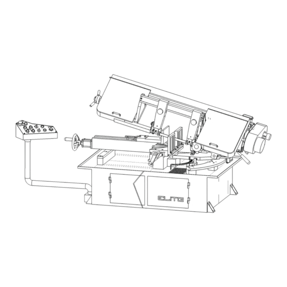
- Page 1 This .pdf document is bookmarked Operating Instructions and Parts Manual Horizontal Band Saw Models EHB-1018VM | EHB-1018VMH ® 427 New Sanford Road LaVergne, Tennessee 37086 Part No. M-891070 www.jettools.com REV C2 09/2018 Ph.: 855-336-4032 Copyright © 2018 JET...
-
Page 2: Warranty And Service
Technical Service by calling 1-855-336-4032, 8AM to 5PM CST, Monday through Friday. WARRANTY PERIOD The general warranty lasts for the time period specifi ed in the literature included with your product or on the offi cial JET branded website, jettools.com. - Page 3 THE ABOVE LIMITATION OR EXCLUSION MAY NOT APPLY TO YOU. JET sells through distributors only. The specifi cations listed in JET printed materials and on offi cial JET website are given as general information and are not binding. JET reserves the right to effect at any time, without prior notice, those alterations ®...
-
Page 4: Table Of Contents
® Do not use this band saw for other than its intended use. If used for other purposes, JET , disclaims any real or implied warranty and holds itself harmless from any injury that may result from that use. - Page 5 10. Make certain the switch is in the OFF position before connecting the machine to the power supply. 11. Make certain the machine is properly grounded. 12. Make all machine adjustments or maintenance with the machine unplugged from the power source. 13.
-
Page 6: Introduction
1,320 The specifi cations in this manual were current at time of publication, but because of our policy of continuous improvement, JET, reserves the right to change specifi cations at any time and without prior notice, without incurring obligations. Horizontal Band Saw... -
Page 7: Uncrating And Assembly
6.0 UNCRATING AND ASSEMBLY 8.0 ELECTRICAL CONNECTIONS Note: Read and understand the entire manual before attempting setup or operation. 1. Finish uncrating the saw and inspect for damage. All electrical connections must be done by a Should any have occurred, contact your local distribu- qualifi... -
Page 8: Auxiliary Coolant Hose
12.0 OPERATING CONTROLS AND ADJUSTMENTS 12.1 REMOVING AND INSTALLING THE BLADE 1. Disconnect the machine from the power source. 2. Raise the saw frame about 6” and close the feed rate lever by turning it clockwise as far as it will go. 3. -
Page 9: Adjusting Blade Guide Brackets
12.2 ADJUSTING BLADE GUIDE BRACKETS The blade guides should be set as close to the vise jaw as possible. The right blade guide bracket (A) Fig. 6, is not adjustable and is set at the factory to clear the right hand vise jaw. -
Page 10: Changing Blade Speed
Speed Adjuster Knob Fig. 9 Fig. 7 12.5 OPERATING VISE The workpiece is placed between the vise jaws with the required amount to be cut-off extending out past the blade. To position the moveable vise jaw (B) instantly, simply turn vise handknob (A) Fig. -
Page 11: Bow Weight Adjustment
Fig. 10 Fig. 11 12.8 SETTING UP THE MACHINE FOR 12.6 BOW WEIGHT ADJUSTMENT OPERATION Bow weight is one of the most important adjustments of Select the proper speed and blade for the type of the saw. If the bow weight is not set properly, one can material you are cutting. -
Page 12: Automatic Shut-Off
12.9 AUTOMATIC SHUT-OFF Each machine and any accessories which are wired into the electrical system are controlled by the start-stop buttons. The machine will automatically shut off when the cut is completed. The lever (A) Fig. 13, for the automatic shut-off, contacts the top of the hydraulic cylinder (B) and shuts off the machine. -
Page 13: Safety Device For Broken Saw Blade
12.14 MITER ANGLE ADJUSTMENT 12.12 SAFETY DEVICE FOR BROKEN SAW BLADE In order to use the mitering function of this saw, fi rst you must release the tension on lever (A) Fig. 18 by pulling When the saw blade breaks during operation, the limit the lever up. -
Page 14: Maintenance
13.0 MAINTENANCE 15.0 REPLACEMENT PARTS — EHB 1018VM and EHB 1018VMH Replacement parts are listed on the following pages. To order parts or reach our service department, call Before doing maintenance on the machine, discon- 1-855-336-4032, Monday through Friday (see our website nect it from the electrical supply by pulling out the plug or switching off the main switch! Failure to for business hours, www.jettools.com). - Page 15 SAW STAND AND BED ASSEMBLY — EHB 1018VM, 1018VMH EHB-1018VM | EHB-1018VMH...
- Page 16 PARTS LIST EHB-1018VM, EHB-1018VMH Index No. Part No. Description Size Qty. EHB916V-64 Fitting EHB916V-65 Tubing 5/16"× 65" EHB1018VM-66 Valve EHB1018VM-67 Feed Knob TS-0209071 Socket Head Cap Screw 3/8 × 1-1/2" EHB1018VM-191 Rack block EHB1018VM-192 Vise jaw Bracket TS-0267041 Set Screw 1/4-20 ×...
- Page 17 Index No. Part No. Description Size Qty. EHB916V-222 Tube Fitting EHB916V-223 Retaining Ring S-17 EHB1018VM-224 Pivot Shaft EHB916V-225 Socket Set Screw 3/8"-16T × 3/8" TS-0680031 Flat Washer 5/16" TS-0051051 Hex Cap Screw 5/16 × 1" EHB916V-232 Motor Plate EHB1018V-233 Rear Pivot Bracket EHB916V-234 Socket Set Screw 1/2"...
- Page 18 Index No. Part No. Description Size Qty. TS-0271031 Socket Set Screw 3/8-16T ×3/8" EHB916V-269 Pivot Shaft EHB1018VM-270 Spindle EHB1018VM-271 Base Assembly 76-1 EHB1018VM-271-1 Base Lid 76-2 EHB1018VM-271-2 Base Lid 76-3 EHB1018VM-271-3 Door 76-4 EHB1018VM-271-4 Wiring box EHB1018VM-272 Sliding Surface TS-0267071 Socket Set Screw 1/4-20 ×...
- Page 19 Index No. Part No. Description Size Qty. 105-1 EHB1018VM-301-1 Raise/Lower/Vise Clamp/Vise Unclamp Switch EHB1018VM-302 Stop Switch EHB1018VM-303 Selection Switch EHB1018VM-304 Emergency Switch EHB916V-305 Indication Light For Power EHB1018VM-306 Control Box 110-1 EHB1018VM-306-1 Tube EHB1018VM-307 Screw 3/16" x 3/8" EHB1018VM-311 Acme Leadscrew Seat TS-0680031 Flat Washer 5/16"...
- Page 20 SAW ARM ASSEMBLY — EHB 1018VM, 1018VMH Horizontal Band Saw...
- Page 21 PARTS LIST SAW ARM — EHB 1018VM, 1018VMH Index No. Part No. Description Size Qty. EHB916V-01 Handwheel EHB916V-01-1 Handwheel handle EHB916V-20 Lock Nut EHB916V-03 Shaft EHB916V-04 Bracket EHB916V-05 Slide EHB916V-06 EHB916V-07 Collar EHB916V-08 Roll pin 5x30 EHB916V-08-1 Roll pin 5x40 TS-0081031 Hex Cap Screw 5/16 x 3/4...
- Page 22 Index No. Part No. Description Size Qty. TS-0060071 Hex Cap Screw 3/8"-16 × 1-1/2" TS-0207021 Socket Head Cap Screw 1/4"-20 × 5/8" TS-0561011 Hex Nut 1/4” EHB916V-47 SB-3/16 Steel Ball 3/16” TS-0270061 Set Screw 5/16"-18 × 5/8" TS-0207021 Socket Head Cap Screw 1/4"-20 ×...
- Page 23 Index No. Part No. Description Size Qty. EHB1018VM-100 Belt (for 1018VM/1018VMH) EHB916V-101 Cable Glands(not show) PG-11 EHB916V-103 Upper Guard EHB916V-109 Lower Guard EHB916V-110 Motor Pulley TS-0270021 Socket Set Screw 5/16-18 ×5/16" EHB916V-112 Pulley TS-0270021 Socket Set Screw 5/16-18 ×5/16" EHB916V-114 5 x 5 x 40 TS-0720081 Lock Washer...
- Page 24 Index No. Part No. Description Size Qty. 156-2 TS-0680011 Washer EHB916V-157 Blade cover EHB916V-158 Special Knob TS-0680041 Flat Washer 3/8" TS-0060031 Hex Head Screw 3/8 x 16 x 3/4” EHB1018V-161 Bracket EHB916V-165 Round Head Screw 3/16 ×3/8" EHB916V-166 Cover L.H. EHB916V-167 Handle TS-081F051...
- Page 25 ELECTRICAL BOX ASSEMBLY — EHB 1018VM 308-1 308-7 308-8 308-2-1 308-13 308-2 308-3 308-11 308-4 308-12 308-5 308-19 308-18 308-6 308-17 308-16 308-15 308-10 308-9 PARTS LIST ELECTRICAL BOX — EHB 1018VM Index No. Part No. Description Size Qty. 308-1 EHB1018VM-308-1 Transformer 230/460/12/24/110V...
- Page 26 ELECTRICAL BOX ASSEMBLY — EHB 1018VMH 308-1 308-7 308-8 308-2-1 308-14 308-2 308-13 308-3 308-11 308-4 308-19 308-12 308-5 308-18 308-6 308-20 308-17 308-16 308-15 308-10 308-9 PARTS LIST ELECTRICAL BOX — EHB 1018VMH Index No. Part No. Description Size Qty.
- Page 27 16.0 WIRING DIAGRAM — EHB 1018VM TO MAIN MOTOR TO COOLANT PUMP TO HYDRAULIC 380V 415V 220V 440V 110V WORK LIGHT PILOT LAMP SENSOR SENSOR MAIN MOTOR SOL1 COOLANT PUMP HYDRAULIC EHB-1018VM | EHB-1018VMH...
-
Page 28: Wiring Diagram
WIRING DIAGRAM — EHB 1018VMH TO MAIN MOTOR TO HYDRAULIC 220V 380V 415V 440V 110V WORK LIGHT RESET SENSOR SENSOR PILOT LAMP MAIN MOTOR COOLANT PUMP SOL1 DOWN SOL2 HYDRAULIC SOL3 VICE CLAMP SOL4 VICE OPEN Horizontal Band Saw... - Page 29 NOTES EHB-1018VM | EHB-1018VMH...
- Page 30 NOTES Horizontal Band Saw...
- Page 31 NOTES EHB-1018VM | EHB-1018VMH...
- Page 32 NOTES Horizontal Band Saw...
Need help?
Do you have a question about the Elite EHB-1018VM and is the answer not in the manual?
Questions and answers