Table of Contents
Advertisement
Advertisement
Table of Contents

Subscribe to Our Youtube Channel
Related Manuals for Jet Elite EHB-8VS


Summary of Contents for Jet Elite EHB-8VS
- Page 1 This .pdf document is bookmarked Operating Instructions and Parts Manual 8-in x 13-in Horizontal Cut-Off Bandsaw Models: EHB-8VS and EHB-8VSM ® 427 New Sanford Road LaVergne, Tennessee 37086 Part No. M-891015 www.jettools.com REV C1 9/2018 Ph.: 855-336-4032 Copyright © 2017 JET...
-
Page 2: Warranty And Service
Technical Service by calling 1-855-336-4032, 8AM to 5PM CST, Monday through Friday. WARRANTY PERIOD The general warranty lasts for the time period specified in the literature included with your product or on the official JET branded website, jettools.com. WHO IS COVERED? This warranty covers only the initial purchaser of the product from the date of delivery. - Page 3 Canada by JPW Industries, Inc. NOTE: JET is a division of JPW Industries, Inc. References in this document to JET also apply to JPW Industries, Inc., or any of its successors in interest to the JET brand.
-
Page 4: Table Of Contents
® Do not use this band saw for other than its intended use. If used for other purposes, JET , disclaims any real or implied warranty and holds itself harmless from any injury that may result from that use. - Page 5 Wear ear protectors (plugs or muffs) during extended periods of operation. Do not operate this machine while tired or under the influence of drugs, alcohol or any medication. 10. Make certain the switch is in the OFF position before connecting the machine to the power supply. 11.
-
Page 6: Introduction
If there are questions or comments, please contact your local supplier or JET. JET can also be reached at our web site: www.jettools.com. Retain this manual for future reference. If the machine transfers ownership, the manual should accompany 5.0 SPECIFICATIONS... -
Page 7: Machine Features
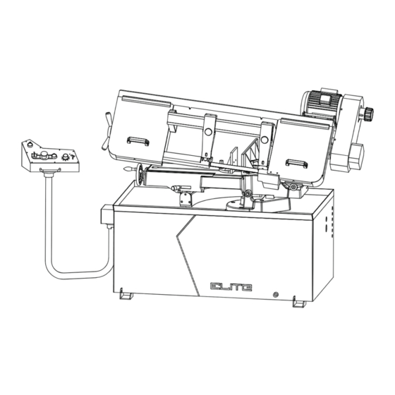
6.0 MACHINE FEATURES 6.2 SAW HEAD Figures 1 and 2 depict the main features of the Model EHB- 8 Horizontal Cut-Off Bandsaw. The machine consists of a The saw head (Figure 2) consists of a drive motor, drive machine base onto which is installed a saw head. pulleys, gearbox, blade wheels, blade guides and supports, control panel, blade tension/blade tracking mechanism, 6.1 MACHINE BASE... -
Page 8: Work Stop
6.3 WORK STOP 7.0 UNPACKING AND ASSEMBLY A work stop (refer to Figure 3) is provided with the machine 7.1 MACHINE SETUP to allow cutting multiple pieces of identical length (refer to The cut-off saw has been pre-adjusted at the factory and Figure 12). -
Page 9: Controls And Indicators
9.0 CONTROLS AND INDICATORS 9.2 BLADE SPEEDS The Model EHB-8 horizontal cut-off bandsaw is equipped 9.1 CONTROL PANEL with electronic variable speed raging from 80-310 FPM. The The operating controls for the cut-off saw are located on the speed change is completed by turning the speed control control panel (Figure 4) and consist of the following controls knob (Figure 5) located to the right of the machine on the and indicators:... -
Page 10: Blade Selection
However, the following procedure will be adequate for break- in of Jet-supplied blades on lower alloy ferrous materials: Clamp a section of round stock in the vise. The stock should be 2 inches or larger in diameter. -
Page 11: Evaluating Cutting Efficiency
11.2 EVALUATING CUTTING EFFICIENCY 11.4 SETTING THE VISE FOR ANGLE CUTS (NON-MITERING VERSION ONLY) Is the blade cutting efficiently? The best way to determine this is to observe the chips formed by the cutting blade. Referring to Figure 9, the vise can be adjusted through a 45-degree arc as follows: If the chip formation is powdery, then the feed is much too light, or the blade is dull. -
Page 12: Setting The Vise For Square Cuts
11.5 SETTING THE VISE FOR SQUARE CUTS The procedure for setting the vise for square cuts is identical to setting for angle cuts (above) except that a machinist’s Never operate the saw without blade covers in place. square is used to set the angle of the fixed vise jaw (A, Fig. 10). -
Page 13: Setting The Work Stop
Referring to Figure 12: Refer to Figures 13 and 14. The work stop is an accessory that is included with the Jet Blade tracking has been set and tested at the factory. EHB-8 Bandsaw. It is used to set up the saw for making Adjustment is rarely required when the blade is used multiple cuts of the same length. - Page 14 Turn the adjustment screws (F) to stop the motion of the blade on the wheel as it gets closer to the wheel shoulder. Put a 6-inch length of paper (J, Fig. 14) between the blade and the wheel as shown (the saw is still turned on).
-
Page 15: Blade Guide Adjustment
12.2 BLADE GUIDE ADJUSTMENT It is always better to try a new blade when cutting performance is poor. If performance remains poor after Referring to Figure 15: changing the blade, check the blade guides for proper The EHB-8 Bandsaw has two adjustable blade guide spacing. -
Page 16: Drive Belt Tension Adjustment
If required, adjust first one guide bearing and blade guide 12.5 VERIFYING ADJUSTMENT ACCURACY assembly then the other as follows: Refer also to Figure 18. Using a 3mm hex wrench, loosen two set screws (A) Test cuts can be used to determine whether or not you have securing the eccentric bushings. -
Page 17: Switch Adjustment
to 1-1/2 inches are exposed on the right side of the 12.6 LIMIT SWITCH ADJUSTMENT eyebolt mount. The saw can now be returned to service. Disconnect the cut-off saw from its electrical power source. Spring Referring to Figure 19: Adjustment Nut Loosen the jam nut and set the adjustment screw so that the limit switch will actuate to the off position when the saw has cut through the workpiece. -
Page 18: Changing The Drive Belt
Using leather gloves to prevent cuts and scratches, Set the arm at the full horizontal position. pull the blade off the drive wheels (H) and out of Open the drive belt cover to expose the drive belt and the blade guides (J). Store the removed blade pulleys. -
Page 19: Replacing The Drive Motor
13.3 REPLACING THE DRIVE MOTOR Clean the chip sludge from the coolant tank. The frequency should be determined by how often the saw is used. Disconnect the cut-off saw from its electrical 15.0 LUBRICATION power source. Lubricate the following components at the specified Referring to Figure 24: frequencies and using the lubricants defined as follows: Remove the drive belt (see Changing the Drive... -
Page 20: Troubleshooting
17.0 TROUBLESHOOTING Fault Probable Cause Suggested Remedy Material loose in vise. Clamp work securely. Incorrect speed or feed. Check Machinist’s Handbook for Teeth too coarse for material. speed/feed appropriate for the Incorrect blade tension. material being cut. Saw blade is in contact with work Check Machinist’s Handbook for piece before the saw is started. - Page 21 Fault Probable Cause Suggested Remedy Blade speed too high for Reduce blade speed and feed pressure. feed pressure. Bad cuts (rough) Blade is too coarse. Replace with finer blade. Blade is binding in the cut. Decrease feed pressure. Blade is twisting Blade tension too high Decrease tension on Blade Blade guides worn...
-
Page 22: Replacement Parts
18.0 REPLACEMENT PARTS EHB-8VS/VSM To order parts or reach our service department, call 1-855-336-4032 Monday through Friday (see our website for business hours, www.jettools.com). Having the Model Number and Serial Number of your machine available when you call will allow us to serve you quickly and accurately. ®... - Page 23 EHB-8VS SAW STAND & BED - PARTS BREAKDOWN EHB-8VS | EHB-8VSM...
- Page 24 EHB-8VS SAW STAND & BED PARTS LIST Index No. Part No. Description Size Qty. TS-1499141 Hex Cap Screw M12x80 TS-1540081 Hex Nut EHB8VS-2A Stand Assembly (Index 2-1 thru 2-5) EHB8VS-2-1 Coolant Pan EHB8VS-2-2 Right Leg EHB8VS-2-3 Left Leg EHB8VS-2-4 Front Panel/Shelf EHB8VS-2-5 Back Door/Shelf TS-0050031...
- Page 25 Index No. Part No. Description Size Qty. 17-6 EHB8VS-17-6 Bracket 17-7 EHB8VS-17-7 TS-1505031 Socket Head Cap Screw M10x25 24-1 TS-2361101 Lock Washer EHB8VS-25 Pivot Shaft Washer EHB8VS-26 Support Bracket 26-1 EHB8VS-26-1 Gap Ring 28-1 EHB8VS-28-1 Tube ID1/2"x2.8tx126cm 1 28-2 EHB8VS-28-2 Hose Clamp Ø19mm 28-3...
- Page 26 Index No. Part No. Description Size Qty. EHB8VS-71 Limit Switch Holder TS-1534042 Pan Head Machine Screw M6x12 EHB8VS-73 Limit Switch TS-1550021 Flat Washer 74-1 TS-1540021 Hex Nut TS-2284302 Pan Head Machine Screw M4x30 EHB8VS-117 Pivot Shaft EHB8VS-402 Swivel Bushing EHB8VS-403 Control Column TS-1490011 Hex Cap Screw...
- Page 27 EHB-8VSM SAW STAND & BED - PARTS BREAKDOWN EHB-8VS | EHB-8VSM...
- Page 28 EHB-8VSM SAW STAND & BED PARTS LIST Index No. Part No. Description Size Qty. TS-1499141 Hex Cap Screw M12x80 TS-1540081 Hex Nut EHB8VSM-6-3 Elbow PT1/2x1/4 EHB8VS-6-4 Coolant Pump 1/8HP,115/230V,1Ph 1 TS-0680021 Flat Washer 1/4" TS-081F052 Pan Head Machine Screw 1/4"-20x3/4 EHB8VS-7 Pivot Shaft EHB8VS-8S...
- Page 29 Index No. Part No. Description Size Qty. TS-1490081 Hex Cap Screw M8x45 EHB8VS-42 Front Moveable Vise Jaw EHB8VS-43 Bushing TS-1550071 Flat Washer TS-1505051 Socket Head Cap Screw M10x35 EHB8VS-46 Washer ø10.5xø27xt3mm EHB8VS-47 Bolt EHB8VS-48 Socket Set Screw M8x30 EHB8VS-46 Washer ø10.5xø27xt3mm EHB8VS-50 Locking Handle...
- Page 30 Index No. Part No. Description Size Qty. EHB8VSM-162 Handle EHB8VSM-164 Slide Base EHB8VSM-165 Stop Bracket EHB8VSM-166 Socket Head Cap Screw M10x40 EHB8VSM-167 Scale EHB8VSM-168 Rivet M2x5 TS-1505131 Socket Head Cap Screw M10x80 169-1 TS-1505041 Socket Head Cap Screw M10x30 EHB8VSM-170 Rotation Base EHB8VSM-171 Bracket...
- Page 31 SAW HEAD (BOTH MODELS) - PARTS BREAKDOWN 354-12 354-11 354-9 354-1 354-8 354-6 354-2 345-4 354-7 354-3 345-2 345-1 351-3 345-3 354-4 354-10 354-5 330-1 351-1 351-2 351S 345S 314-2 314-1 360-1 314-5 314-6 355-1 314-4 317 316 314-3 316-1 306-1 220-6 315-1...
- Page 32 SAW HEAD (BOTH MODELS) PARTS LIST Index No. Part No. Description Size Qty. EHB8VS-200 Blade Guard EHB8VS-202 Knob M6-1.0Px10L TS-1504051 Socket Head Cap Screw M8x25 TS-1551061 Lock Washer TS-1550061 Flat Washer EHB8VS-207 Knob TS-1550071 Flat Washer EHB8VS-209 Blade Guide Support Arm 209-1 EHB8VS-209-1 Blade Direction Label...
- Page 33 Index No. Part No. Description Size Qty. TS-2311061 Hex Nut M6-1.0P EHB8VS-306 Right Blade Wheel Cover 306-1 EHB8VS-306-1 Padding Strip TS-1490031 Hex Cap Screw M8x20 EHB8VS-308 Washer ø16xø30xt3mm BB-6205VV Bearing 6205-2RS EHB8VS-310 Idler Wheel EHB8VS-311 Shaft EHB8VS-312 Handle TS-0561031 Hex Nut 3/8"-16 EHB8VS-314 Body Frame...
- Page 34 Index No. Part No. Description Size Qty. EHB8VS-345 Pulley Guard 345-1 EHB8VS-345-1 Pulley Cover 345-2 EHB8VS-345-2 Knob 345-3 EHB8VS-345-3 Bracket 345-4 EHB8VS-345-4 Cross Head Screw M5x8 EHB8VS-350 Belt V-330 351S EHB8VS-351S Variable Speed Pulley Set 351-1 EHB8VS-351-1 Motor Pulley 351-2 EHB8VS-351-2 Gear Box Pulley 351-3...
- Page 35 ELECTRIC ASSEMBLY Index No. Part No. Description Size Qty. EHB8VS-5-1 Fuse Base EHB8VS-5-2 Fuse 220V 1A 5-2-1 EHB8VS-5-2-1 Fuse 110V 2A EHB8VS-5-3 Aluminum Rail EHB8VS-5-4 Magnetic Contactor CU-18 EHB8VS-5-5 Overload Relay RHU-10K1 EHB8VS-5-6 Pump Contactor EHB8VS-5-7 Limit Switch TM1309 5-12 EHB8VS-5-12 Transformer 110/220/24V...
-
Page 36: Wiring Diagram
19.0 WIRING DIAGRAM EHB-8 1Ø∼ L 60HZ 110/220V 110V-2A 220V-1A G 0V FR:Overload FU1:24V-2A FUSE TC:Transformer SB1:Emergency Stop SB3:Start Switch SB4:Pump Switch KM1:Contactor KM2:PUMP Contactor L:Signal SQ1:Limit Switch(MET1653) FU2:220V-1A FUSE FU3:110V-2A FUSE M1:MAIN MOTOR M2:COOLANT PUMP MOTOR PE:GROUND 1∼ 1/8HP 1-1/2HP 110/220/60HZ 110/220/60HZ...
Need help?
Do you have a question about the Elite EHB-8VS and is the answer not in the manual?
Questions and answers