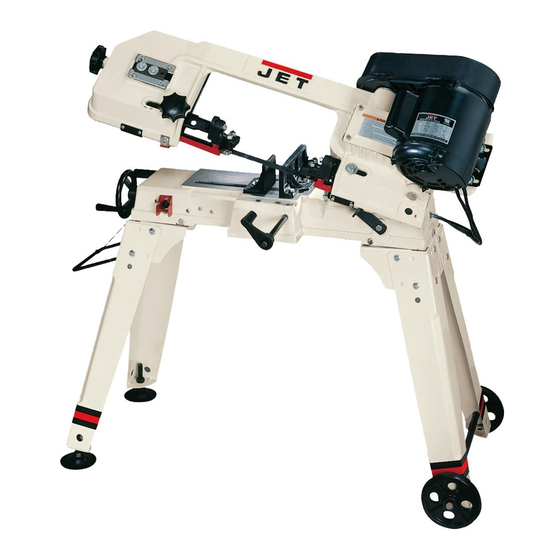
Jet HVBS-56M Owner's Manual
Jet tools owner manual horizontal/vertical bandsaw hvbs-56m
Hide thumbs
Also See for HVBS-56M:
- Brochure (56 pages) ,
- Operating instructions and parts manual (24 pages) ,
- Operating instructions and parts manual (24 pages)
Table of Contents

Summary of Contents for Jet HVBS-56M
- Page 1 HVBS-56M Horizontal/Vertical Bandsaw JET EQUIPMENT & TOOLS, INC. A WMH Company www.jettools.com OWNER'S MANUAL P.O. BOX 1349 Auburn, WA 98071-1349 e-mail jet@jettools.com Phone:253-351-6000 Fax: 1-800-274-6840 M-414458 12/2000...
-
Page 2: Warranty
Important Information 1-YEAR LIMITED WARRANTY REPLACEMENT PARTS Replacement parts for this tool are available directly from JET Equipment & Tools. To place an order, call 1-800-274-6848. Please have the following information ready: 1. Visa, MasterCard, or Discover Card number 2. Expiration date 3. -
Page 3: Warnings
Never attempt any operation or adjustment if the procedure is not understood. Keep fingers away from the blade when the machine is running. Never hand hold material with the saw in the horizontal position. Always use the vise and clamp it securely. -
Page 4: Table Of Contents
The specifications in this manual are given as general information and are not binding. JET Equipment & Tools reserves the right to effect, at any time and without prior notice, changes or alterations to parts, fittings, and accessory equipment deemed necessary for any reason whatsoever. HVBS-56M Page... -
Page 5: Unpacking & Clean-Up
4mm Angle Hex Wrench Ratchet and Sockets will Speed Assembly Assembly 1. With the help of another person turn the saw over so that it rests on the motor and saw bow, Figure 1. Place it on a piece of cardboard, or a surface that will not damage the saw. - Page 6 Secure wheels with two split pins (C, Fig. 3). 9. Carefully turn the saw onto its stand and adjust the feet so the bed is level. 10. Put the handle (A, Fig. 4) through holes in the stand legs opposite of the wheel assembly and secure with split pins.
-
Page 7: Vertical Cutting Plate Assembly
V-belt (C, Fig.5) on both pulleys. 13. Attach the tension bracket (D, Fig. 5) to the saw bow with one 5/16”x3/4” hex head bolt and flat washer (E, Fig. 5). 14. Connect the two tension brackets with one 5/16”x3/4”... -
Page 8: Electrical Connections
4. Remove two screws (D, Fig. 7) and plate (E, Fig. 7). 5. Guide blade through slot in table (A, Fig. 8) and fasten table with two screws (B, Fig. 8). 6. Fasten support bracket to underside of table using screw (C, Fig. 8) and hex nut. 7. -
Page 9: Changing Blade Speed
6. Close pulley cover and connect to power source. The general rule for band saw blade speed is the harder the material being cut, the slower the blade speed. Reference Figure 11 for a guide to blade speed for a type of material being cut. -
Page 10: Changing Blades
Changing Blades 1. Disconnect machine from the power source. 2. Raise the saw arm to the vertical position and lock in place with lock lever. 3. Open blade cover by removing the small knob found on the topside of the bow. -
Page 11: Adjusting Blade Tracking
1. Confirm that blade tension is set properly. To adjust, see section titled " Adjusting Blade Tension". 2. Make sure the saw is in its slowest speed, see “Changing Blade Speeds”. 3. Move saw arm to the vertical position and lock in place with the lock lever. -
Page 12: Adjusting Automatic Shut-Off
Adjusting Automatic Shut-Off The saw should stop after the cut has been completed: If the saw completes the cut and continues to run, adjust the stop tip (A, Fig. 17) down. If the saw shuts off before the cut is complete, adjust the stop tip (A, Fig. -
Page 13: Breakdown For Bow Assembly
Breakdown for Bow Assembly... -
Page 14: Breakdown For Base Assembly
Breakdown for Base Assembly... -
Page 15: Parts List
Parts List for the HVBS-56M Bandsaw Index Part 1...TS-0051031 ...Hex Cap Bolt... 5/16”x3/4” ... 4 2...TS-0561011 ...Hex Nut... 1/4”... 1 3...TS-0680021 ...Flat Washer... 1/4”... 5 4...HVBS56M-04 ...Stand Leg ..4 4-1...HVBS56M-04-1 ...Cross Brace ..2 5...HVBS56M-05 ...Washer ..6 6...HVBS462-006 ...Cotter Pin... - Page 16 78 ...TS-0680031 ...Flat Washer... 5/16”... 2 79 ...HVBS462-079 ...Blade Tension Knob ... 3/8”... 1 80 ...HVBS462-080 ...Spring ..1 81 ...HVBS56M-081 ...Saw Bow..1 82 ...HVBS56M-082 ...Washer ..1 83 ...TS-0070031 ...Cap Screw ... 1/2”x1-1/2” ... 2 84 ...HVBS56M-084 ...Motor Mount Plate...
-
Page 17: Wiring Diagram
Index Part 99 ...HVBS462-099 ...Spacer ..1 100 ...HVBS462-100 ...Flat Cross Head Screw... 5/32”x3/8” ... 8 101 ...HVBS462-101 ...Worm Gear Pulley..1 102 ...TS-0720081 ...Lock Washer ... 5/16”... 2 103 ...HVBS462-103 ...Blade Tension Sliding Plate..1 104 ...TS-0270051 ...Socket Set Screw... 5/16”x1/2” ... 3 105 ...HVBS462-105 ...Spring Pin ...


Need help?
Do you have a question about the HVBS-56M and is the answer not in the manual?
Questions and answers