Table of Contents
Advertisement
This .pdf document is bookmarked
Operating Instructions and Parts Manual
™
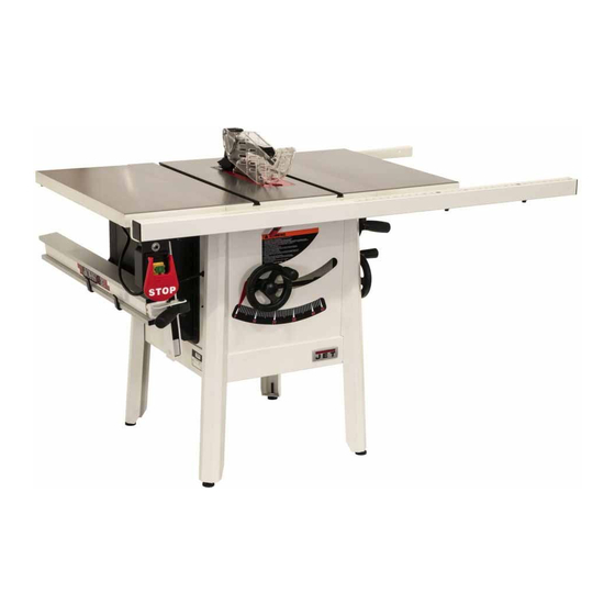
ProShop II
10-inch Table Saw
Model JPS2-115, JPS2-230
shown with cast wings, 52" rail set, and extension table
JET
427 New Sanford Road
LaVergne, Tennessee 37086
Part No. M-725000
Ph.: 800-274-6848
Edition 1 09/2017
www.jettools.com
Copyright © 2017 JET
Advertisement
Table of Contents

Related Manuals for Jet JPS2-115


Summary of Contents for Jet JPS2-115
- Page 1 This .pdf document is bookmarked Operating Instructions and Parts Manual ™ ProShop II 10-inch Table Saw Model JPS2-115, JPS2-230 shown with cast wings, 52” rail set, and extension table 427 New Sanford Road LaVergne, Tennessee 37086 Part No. M-725000 Ph.: 800-274-6848 Edition 1 09/2017 www.jettools.com...
-
Page 2: Important Safety Instructions
Personal safety • Stay alert, watch what you are doing and use common sense when operating a power tool. Do not use a power tool while you are tired or under 1.0 IMPORTANT SAFETY the influence of drugs, alcohol or medication. A moment of inattention while operating power tools INSTRUCTIONS may result in serious personal injury. -
Page 3: Specific Safety Warnings For Table Saws
• and alignment can make the riving knife ineffective Store idle power tools out of the reach of in reducing the likelihood of kickback. children and do not allow persons unfamiliar with the power tool or these instructions to • For the riving knife and anti-kickback pawls to Power tools... - Page 4 • resawing cuts. A featherboard helps to control the Never reach around or over a rotating saw workpiece in the event of a kickback. blade. Reaching for a workpiece may lead to accidental contact with the moving saw blade. • Use extra caution when making a cut into blind areas of assembled workpieces.
- Page 5 Do not use this table saw for other than its intended Always use saw blades with correct size and use. If used for other purposes, JET disclaims any shape (diamond versus round) of arbor holes. Saw blades that do not match the mounting...
-
Page 6: Table Of Contents
2.0 Table of contents Section Page 1.0 IMPORTANT SAFETY INSTRUCTIONS ....................2 1.1 General Safety Warnings ........................2 1.2 Specific Safety Warnings for Table Saws ..................3 2.0 Table of contents ............................ 6 3.0 About this manual ..........................7 4.0 Table Saw terminology........................... 8 5.0 Specifications ............................ -
Page 7: About This Manual
Additional knowledge can be obtained from experienced users, trade articles, or website forums. Whatever accepted methods are used, always make personal safety a priority. If there are questions or comments, please contact your local supplier or JET. JET can also be reached at our web site: www.jettools.com. -
Page 8: Table Saw Terminology
– always use appropriate the kerf opening in the workpiece during a cutting devices to feed the workpiece through the saw operation. (JET table saws use the superior Riving blade during cutting operations.) Knife system instead.) Kerf: The resulting cut or gap made by a saw Standard Kerf: 1/8"... -
Page 9: Specifications
5.0 Specifications Table 1 Model number JPS2-115 JPS2-230 Stock number – saw only 725000 725001 (see Table 2 below for kit configurations) Motor and Electricals Motor type Totally enclosed, fan cooled, induction Horsepower 1.75 HP Motor phase 1 PH Motor voltage... -
Page 10: Kit Configurations
= not applicable The specifications in this manual were current at time of publication, but because of our policy of continuous improvement, JET reserves the right to change specifications at any time and without prior notice, without incurring obligations. -
Page 11: Setup And Assembly
Read understand assembly instructions before attempting assembly. Failure to comply may cause serious injury. 6.0 Setup and assembly 6.1 Shipping contents See Figures 6-1 and 6-2. NOTE: Some parts may have come pre-assembled to the table saw. Table saw with on/off switch (not shown) Blade (preinstalled on saw) Table insert (preinstalled on saw) Arbor wrench (preinstalled on tool holder) -
Page 12: Tools Required For Assembly
6.2 Tools required for assembly Install both screws first, then tighten with 5mm hex wrench. (Note: If more clearance is Hex (Allen) wrenches: 4, 5, 6mm needed to insert a screw, see sect. 6.6 to Open end wrenches: 10, 13mm temporarily mount a handwheel and tilt the Cross point (Phillips) screwdriver trunnion out of the way.) -
Page 13: Handwheels
Method 1 (Figure 6-5): Shift extension wing so it is slightly above saw table surface. Begin by tightening the screws beneath extension wing that secure it to saw table. Tighten these just enough to hold wing in place but loose enough to change wing height by tapping on it. -
Page 14: Wood Extension Table
(not included) and secured with a hose clamp. secure. Note: Dryer vent hose is not acceptable for this purpose. An extensive line of JET dust collectors is available; contact your dealer or visit our website for information. 6.12 Riving knife See Figure 6-9. -
Page 15: Blade Guard
6.15 Blade installation/replacement When installing or changing blades, always disconnect saw from power source. Failure to comply may cause serious injury. Disconnect machine from power source. Using the handwheels, raise blade arbor fully and lock saw at zero-degrees by tightening lock knob at center of handwheel. -
Page 16: Miter Gauge
7.0 Electrical connections The JPS2-115 table saw is wired for 120-volt only. The JPS2-230 is wired for 230-volt only. The table saw comes with a plug designed for use on a circuit with a grounded outlet that looks like the one pictured in either A or D, Figure 7-1. -
Page 17: Overload Reset Button
7.2 Overload reset button Check with qualified If saw becomes overloaded and the motor shuts electrician service personnel off, push re-set button above switch (Figure 7-2) to grounding instructions are not completely restart. If overloading happens frequently, consult understood, or if in doubt as to whether the the Troubleshooting section in this manual. -
Page 18: Adjustments
Figure 7-3 8.0 Adjustments 8.1 Blade raising/tilt mechanism Figure 8-2 Never try to force the tilting If adjustment is required: mechanism past the 45º or 90º stops. This may cause blade misalignment. Remove motor cover on left side. See Figure 8-1. Back out the setscrew in the 90°... -
Page 19: Riving Knife Alignment
Figure 8-5 8.3 Riving knife alignment 8.3.1 Lateral alignment Figure 8-7 Saw blade and riving knife must be as closely 8.3.2 Blade proximity alignment aligned possible (lateral alignment) The gap between saw blade and riving knife must prevention of kickback. This should be checked be between 3mm (0.12in.) and 8mm (0.32in.). -
Page 20: Belt Adjustment/Replacement
Retighten mounting screws firmly. 8.4 Table to blade alignment Verify the alignment, angle pointer setting, Refer to Figures 8-9 and 8-10. fence setting, etc. Make further adjustments as needed. The table has been set square with the blade by the manufacturer and no adjustment is necessary 8.5 Belt adjustment/replacement now. -
Page 21: Operations
9.0 Operations NOTE: The following Figures are general in nature and may not show your particular saw model. Familiarize yourself with the location and operation of all controls and adjustments and the use of accessories such as miter gauge and rip fence. 9.1 Kickbacks Serious injury can result from kickbacks which occur when a workpiece binds on the saw blade or... -
Page 22: Rip Sawing
9.2 Rip sawing Ripping is where the workpiece is fed with the grain into the saw blade using the fence as a guide and a positioning device to ensure the desired width of cut (Figure 9-3). Figure 9-4 In ripping, use one hand to hold the board down against the fence or fixture, and the other to push it into the blade between blade and fence. -
Page 23: Resawing
Figure 9-8 Figure 9-6 Crosscutting should never be done freehand nor When ripping long boards, use a support at front of should the fence be used as an end stop unless an table (A, Figure 9-6), such as a roller stand, and a auxiliary block (A, Figure 9-9) is clamped to the support or "tailman"... -
Page 24: Bevel And Miter Operations
Note: When making compound miters (with blade To improve the effectiveness of the miter gauge in crosscutting, some users mount an auxiliary tilted) use the miter gauge in the right hand slot to wooden extension face (A, Figure 9-10) with a provide more hand clearance and safety. -
Page 25: Safety Devices
Never use a dado head in a tilted position. Never operate the saw without the blade guard, riving knife and anti-kickback pawls for operations where they can be used. 10.0 Safety devices Feather board The feather board (Figure 10-1) should be made of straight grain hardwood approximately 1"... -
Page 26: User-Maintenance
Always disconnect power to enhance the functionality of your table saw. the machine before performing maintenance. Contact your dealer to order, or call JET at the Failure to do this may result in serious phone number on the cover. personal injury. -
Page 27: Troubleshooting Jps2 Proshop Ii
Model Number and Serial Number of your machine available when you call will allow us to serve you quickly and accurately. Non-proprietary parts, such as fasteners, can be found at local hardware stores, or may be ordered from JET. Some parts are shown for reference only, and may not be available individually. -
Page 28: Motor And Trunnion - Exploded View
14.1.1 Motor and Trunnion – Exploded View... -
Page 29: Motor And Trunnion - Parts List
14.1.2 Motor and Trunnion – Parts List Index No Part No Description Size 1 ....6291479 ....Key, Dbl Rd Hd ............5x5x30mm ....1 2 ....JPS10TSC-102 ..Motor Pulley ....................1 3 ....TS-2276081 ....Socket Set Screw ............ M6-1.0Px8 ....2 6 .... - Page 30 Index No Part No Description Size 59 ....TS-1504071 ....Socket Head Cap Screw ......... M8-1.25Px35 ....2 60 ....JPS10TSC-160 ..Hose ................ 2.5 ......... 1 61 ....JWP12-118 ....Key, Dbl Rd Hd ............4x4x8mm ...... 2 62 ....JPS10TSC-162 ..Plate....................... 1 63 ....
- Page 31 Index No Part No Description Size 112 .... JPS10TSC-1112 ..Hose Clamp ............. 60-80mm ....... 1 113 .... JPS10TSC-1113 ..Dust Chute ............... 1-1/2”to 4" ..... 1 114....JPS10TS-SHA ... Side Handwheel Assembly (#114-1, 93-1, 93-2, 93-4) ........1 114-1 ..JPS10TS-168 .... Handwheel (Not shown) ................1 115 ....
-
Page 32: Table And Cabinet– Exploded View
14.2.1 Table and Cabinet– Exploded View... -
Page 33: Table And Cabinet– Parts List
32 ....JPS10TSC-232 ..Angle Scale ....................1 33 ....LM000310 ....Warning Label ....................1 34 ....LM000311 ....ID Label, JPS2-115 (not shown) ..............1 ....LM000314 ....ID Label, JPS2-230 (not shown) ..............1... -
Page 34: Stand Assembly - Exploded View
14.3.1 Stand Assembly – Exploded View 14.3.2 Stand Assembly – Parts List Index No Part No Description Size 1 ....JPS10TSC-301 ..Leg ......................... 4 2 ....TS-1550041 ....Flat Washer ............. M6 ......... 8 3 ....TS-1482031 ....Socket Head Cap Screw ......... M6-1.0x16 ..... 8 4 .... -
Page 35: Switch Assembly - Exploded View
14.4.1 Switch Assembly – Exploded View 14.4.2 Switch Assembly – Parts List Index No Part No Description Size 1 ....JPS10TSC-401 ..Magnetic Switch Kit ..........120V ......1 ....JPS10TSC-401A ..Magnetic Switch Kit ..........230V ......1 2 ....JPS10TSC-402 ..Switch Box ..................... 1 3 .... -
Page 36: Blade Guard Assembly - Exploded View
14.5.1 Blade Guard Assembly – Exploded View... -
Page 37: Blade Guard Assembly - Parts List
14.5.2 Blade Guard Assembly – Parts List Index No Part No Description Size 1 ....JPS10TSC-501 ..Right Side Blade Guard ................. 1 2 ....JPS10TSC-502 ..Screw ......................4 3 ....JPS10TSC-503 ..Left Side Blade Guard ................... 1 4 .... -
Page 38: Miter Gauge Assembly - Exploded View
14.6.1 Miter Gauge Assembly – Exploded View 14.6.2 Miter Gauge Assembly – Parts List ....JPS10TSC-MG ..Miter Gauge Assembly (#1 thru 13) ............... 1 1 ....JPS10TS-327 .... Handle ......................1 2 ....TS-0680041 ....Flat Washer ............. 3/8” ........ 1 3 .... -
Page 39: Electrical Connections For Jps2
15.0 Electrical Connections for JPS2 230V 120V 230V 120V OVERLOAD PROTECTOR OVERLOAD PROTECTOR 9AMP 18AMP LINE LOAD LINE LOAD Magnetic Switch Magnetic Switch KJD17B-230V KJD17B-120V SJT 14AWG*3C SJT 14AWG*3C 230V 120V MOTOR MOTOR... -
Page 40: Warranty And Service
JET sells through distributors only. The specifications listed in JET printed materials and on official JET website are given as general information and are not binding. JET reserves the right to effect at any time, without prior notice, those alterations to parts, fittings, and accessory equipment which they may deem necessary for any reason whatsoever. - Page 41 This page intentionally left blank.
- Page 42 This page intentionally left blank.
- Page 43 This page intentionally left blank.
- Page 44 427 New Sanford Road LaVergne, Tennessee 37086 Phone: 800-274-6848 www.jettools.com...
Need help?
Do you have a question about the JPS2-115 and is the answer not in the manual?
Questions and answers