Table of Contents
Advertisement
Quick Links
Advertisement
Table of Contents

Related Manuals for Tenma 72-1025


Summary of Contents for Tenma 72-1025
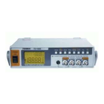
- Page 1 Benchtop LCR Meter AUTO RS232 HOLD FREQ RANGE L/C/R ALWAYS DISCHARGE THE CAPACITOR BEFORE TESTING FORCE SENSE SENSE FORCE RS232 Model 72-1025 Tenma Test Equipment 405 S. Pioneer Blvd. Springboro, OH 45066 www.tenma.com...
-
Page 2: Table Of Contents
Contents Safety ....................1 Introduction................... 3 Impedance theory................. 4 Impedance ................4 Measuring impedance ............... 7 Parasitic ..................7 Real, effective, and indicated values ......... 8 Component dependency factors ..........10 Measurement methods.............16 Getting Started..................17 Front Panel Illustration .............17 Rear Panel Illustration ..............18 LCD Display Illustration ............19 Measurement Preceedure ..............21 Inductance Measurement ............22... - Page 3 Accessories ..................39 Standard Accessories: ..............39 Optional Accessories: ..............40 MAINTENANCE ..................41 Service ..................41 Cleaning the Meter ..............41 Selecting input line voltage............42 Fuse Replacement ..............44...
-
Page 4: Safety
SAFETY Read "SAFETY INFORMATION" before using this meter. NOTE The meter is a bench type instrument for testing inductance, capacitance and resistance. If this device is damaged or something is missing, contact the place of purchase immediately. This manual contains information and warnings must be followed to ensure safe operation as well as to maintain the meter in a safe condition. - Page 5 SAFETY INFORMATION To ensure that you use this device safely, follow the safety guidelines listed below: 1. Before applying power, ensure that power cord and the proper line voltage indicated for power source being used. 2. This product is grounded through the ground conductor of the power cord.
-
Page 6: Introduction
INTRODUCTION This 19,999-count L/C/R meter is a special microprocessor-controlled meter for measuring functions of inductance, capacitance and resistance. Extremely simple to operate, the instrument not only takes absolute parallel mode measurements, but is also capable of series mode measurement. The meter provides direct and accurate measurement of inductors, capacitors and resistors with selectable test frequencies. -
Page 7: Impedance Theory
IMPEDANCE THEORY Impedance Impedance is an important parameter used to characterize electronic circuits, components, and the materials used to make components. Impedance (Z) is generally defined as the total opposition a device or circuit offers to the flow of an alternating current (AC) at a given frequency, and is represented as a complex quantity, which is graphically shown on a vector plane. - Page 8 Figure- 3. Expression of series and parallel combination Reactance takes two forms - inductive (X ) and capacitive (Xc). By definition, X =2πfL and Xc=1/(2πfC), where f is the frequency of interest, L is inductance, and C is capacitance. 2πf can be substituted for by the angular frequency (ω:omega) to represent X =ωL and Xc=1/(ωC).
- Page 9 a dimensionless unit and is expressed as Q=X/R. From Figure-5, you can see that Q is the tangent of the angle θ. Q is commonly applied to inductors; for capacitors the term more often used to express purity is dissipation factor (D). This D quantity is simply the reciprocal of Q. It is the tangent of the complementary angle of θ.
-
Page 10: Measuring Impedance
Measuring impedance To find the impedance, we should measure two values at least because impedance is a complex quantity. Many modern impedance instruments measure the real and the imaginary parts of an impedance vector and then convert them into the desired parameters such as |Z|, θ , L, C, R, X, It is only necessary to connect the unknown component, circuit, or material to the instrument. -
Page 11: Real, Effective, And Indicated Values
Real, effective, and indicated values A thorough understanding of real, effective, and indicated values of a component, as well as their significance to component measurements, is essential before you proceed with making practical measurements. A real value is the value of a circuit component (resistor, inductor or capacitor) that excludes the defects of its parasites. - Page 12 The indicated value is the value obtained with and displayed by the measuring instrument; it reflects the instrument’s inherent losses and inaccuracies. Indicated values always contain errors when compared to true or effective values. They also vary intrinsically from one measurement to another;...
-
Page 13: Component Dependency Factors
Component dependency factors The measured impedance value of a component depends on several measurement conditions, such as frequency, test signal level, and so on. Effects of these component dependency factors are different for different types of materials used in the component, and by the manufacturing process used. - Page 14 Figure- 10. Capacitor frequency response Figure- 11. Indicator frequency response...
- Page 15 Test signal level The test signal (AC) applied may affect the measuring result for some components. For example, ceramic capacitors are test signal voltage dependent as shown in Figure -12. This dependency varies depending on the dielectric constant (K) of the material used to make the ceramic capacitor.
- Page 16 DC bias DC bias dependency is very common in semiconductor components such as diodes and transistors. Some passive components are also DC bias dependent. The capacitance of a high-K type dielectric ceramic capacitor will vary depending on the DC bias voltage applied, as shown in Figure-14.
- Page 17 Temperature Most types of components are temperature dependent. The temperature coefficient is an important specification for resistors, inductors and capacitors. Figure -16 shows some typical temperature dependencies that affect ceramic capacitors with different dielectrics. Figure- 16. Temperature dependency of ceramic capacitors...
- Page 18 Other dependency factors: Other physical and electrical environments, e.g., humidity, magnetic fields, light, atmosphere, vibration, and time may change the impedance value. For example, the capacitance of high-K type dielectric ceramic capacitors decreases with age as shown in Figure-17. Figure- 17. Aging dependency of ceramic capacitors...
-
Page 19: Measurement Methods
Measurement methods There are many measuring methods to choose for measuring impedance, each of which has advantages and disadvantages. You must consider your measurement requirements and conditions, and then choose the most appropriate method, while considering such factors as frequency coverage, measurement range, measurement accuracy, and ease of operation. -
Page 20: Getting Started
GETTING STARTED Front Panel Illustration 3 4 5 8 9 10 AUTO RS232 HOLD FREQ RANGE L/C/R ALWAYS DISCHARGE THE CAPACITOR BEFORE TESTING FORCE SENSE SENSE FORCE RS232 Figure- 19. Front panel POWER SWITCH: Turns power ON/OFF. LCD display RS232: Toggles RS232 function ON/OFF. HOLD (REC): Press this button to hold data. -
Page 21: Rear Panel Illustration
Rear Panel Illustration Figure- 20. Rear Panel. 1. Optical RS-232 interface port. 2. Power cord socket. 3. Line voltage selector and fuse holder: to select line voltage and fuse replacement. CAUTIONS In order to avoid damaging this instrument, make sure that the unit is set to the correct line voltage for your area. -
Page 22: Lcd Display Illustration
LCD Display Illustration 3 4 6 10 RS232 Figure- 21. LCD Display. AUTO: Auto-range indicator LCR: L, C or R function indicator MAX: Maximum reading indicator AVG: Average reading indicator REL: Relative mode indicator MIN: Minimum reading indicator DH: Data hold indicator Θ: Phase angle indicator Q: Quality factor indicator 10. - Page 23 : Non-used. : Non-used. 21. PAL: Parallel mode indicator 22. SER: Series mode indicator 23. MkΩ: Resistance (Ohm) indicator : Inductance (Henry) indicator : Capacitance (Farad) indicator : RS232 indicator Special Indication Characters : Indicates short connectors : Indicates open connectors : Indicates calibration mode : Indicates damaged or open fuse...
-
Page 24: Measurement Preceedure
OPERATION Caution When measuring within a circuit, the circuit must be de-energized before connecting the test leads. If the instrument is used in a dusty environment, it should be wiped and cleaned regularly. Do not leave the instrument exposed to direct heat from the sun or other heat source for long periods. -
Page 25: Inductance Measurement
Inductance Measurement Press “L/C/R” button to select inductance measurement. Connect the BNC ends of red clip or SMD Tweezers to “SENSE +” and “FORCE +”, respectively. Connect the BNC ends of black clip or SMD Tweezers to “SENSE -” and “FORCE -”, respectively. Connect the test clips to the component leads as required, or use SMD Tweezers to measure SMD type component. -
Page 26: Capacitance Measurement
Capacitance Measurement Press “L/C/R” button to select capacitance measurement. Connect the BNC ends of red clip or optional SMD Tweezers to “SENSE +” and “FORCE +”, respectively. Connect the BNC ends of black clip or optional SMD Tweezers to “SENSE -” and “FORCE -”, respectively. Connect the test clips to the component leads as required, or use optional SMD Tweezers to measure SMD type component. -
Page 27: Resistance Measurement
Resistance Measurement Press “L/C/R” button to select Resistance measurement. Connect the BNC ends of red clip or optional SMD Tweezers to “SENSE +” and “FORCE +”, respectively. Connect the BNC ends of black clip or optional SMD Tweezers to “SENSE -” and “FORCE -”, respectively. Connect the test clips to the component leads as required, or use optional SMD Tweezers to measure SMD type component. -
Page 28: Operating Instructions
OPERATION Data Hold This data hold function allows the operator to freeze the display. To enter this mode, press the "HOLD" pushbutton; press again to release. Static Recording™ Press the "REC" pushbutton for more than one second to enter the static recording mode. -
Page 29: Dissipation Factor / Quality Factor/ Phase Angle
Dissipation Factor / Quality Factor/ Phase Angle The "D/Q/Θ" value can be displayed interchangeably by pressing the "D/Q/Θ" button when the meter is set to Inductance or Capacitance mode. It does not apply to resistance measurement. Test Frequency Default test frequency is 1KHz. Push "FREQ" key to select the desired test frequency for 10kHz, 100Hz, 120Hz, or 1kHz. -
Page 30: Tolerance Mode
Tolerance Mode This function is designed for convenient component sorting. There are four tolerance ranges; 1%, 5%, 10% and 20%. To enter tolerance mode, select a component that is to be used as the standard, and connect to the test probes, then press the "TOL" pushbutton to set this value, as the standard reference tolerance. -
Page 31: Auto / Manual Range
Auto / Manual Range Auto-range mode is default status when the meter is powered on. For specific measurement, press "AUTO" button to select manual ranging. To return to the auto-ranging mode, press and hold the "AUTO" button for more than one second. Automatic Fuse Detection When the meter detects that the protective fuse is open, the "FUSE"... -
Page 32: Parallel / Series Mode
Parallel / Series Mode The meter is capable of Parallel and Series measurement mode. The parallel mode is default for Capacitance and Resistance measurements, and the series mode is default for Inductance measurement. Press "L/C/R" button for more than 1 second to toggle "SER" and "PAL" mode. - Page 33 Inductance 100Hz 120Hz 1KHz 10KHz Range Series Parallel Series Parallel Series Parallel Series Parallel √ √ √ √ 1000H √ √ √ √ √ √ 200/100H * √ √ √ √ √ √ √ √ √ √ √ √ √ ◊...
-
Page 34: Short/ Open Calibration
Short/ Open Calibration OPEN/ SHORT Calibration is available to all ranges. Simply press and hold "CAL" button for more than one second to enter the calibration mode and calibration prompts will be displayed. Follow the prompts for open connector ( ) or short connector ( ) connection and press the "CAL"... -
Page 35: Communication
Communication This meter provides communication capability, with the use of an optional RS232 package and optically isolated cable and software. Refer to the following procedure to set up the communication between the meter and a personal computer. Attache the appropriate end of the interface cable to the meter, with the text side facing up. -
Page 36: General Specifications
GENERAL SPECIFICATIONS Parameters Measured L/C/R/D/Q/ Θ Measuring Circuit Mode Inductance (L) –Defaults to series mode Capacitance/ Resistance (C/R) -Defaults to parallel mode L/C/R: Maximum display 19999 Displays D/Q: Maximum display 999 (Auto Range). Auto & Manual Ranging Mode 4 BNC terminals with one ground terminal Measuring Terminals 100Hz=100 Hz Test Frequency... -
Page 37: Electrical Specifications
ELECTRICAL SPECIFICATIONS Accuracy is expressed as: ± (% of reading + no. of least significant digits) at 23℃±5℃and <75% R.H. Resistance (Parallel mode) Test Frequency: 100 / 120 Hz Maximum Accuracy Specified Note Range Display 100 Hz/ 120Hz 10MΩ 9.999MΩ 0.6%+5 After open cal. -
Page 38: Capacitance (Parallel Mode)
Capacitance (Parallel mode) Test Frequency: 100 / 120 Hz Maximum Accuracy Spec. Note Range Display Capacitance 10mF 19.99mF 2.5%+5 5%+100/Cx+5 After short (DF<0.1) (DF<0.1) cal. 0.6%+5 1%+100/Cx+5 After short 1000 μ F 1999.9 μ F (DF<0.1) (DF<0.1) cal. 0.4%+3 0.4%+100/Cx+5 200 μ... - Page 39 Test Frequency: 10 KHz Maximum Accuracy Spec. Note Range Display Capacitance 50 μ F 50.0 μ F 2.0%+10 8%+100/Cx+10 After short (DF<0.1) (DF<0.1) cal. 20 μ F 19.999 μ F 2.0%+6 3.0%+100/Cx+8 After short (DF<0.2) (DF<0.2) cal. 2000nF 1999.9nF 1.0%+5 1.0%+100/Cx+6 (DF<0.5) (DF<0.5)
-
Page 40: Inductance (Series Mode)
Inductance (Series mode) Test Frequency: 100 / 120Hz Maximum Accuracy (DF<0.5) Spec. Note Range Display Inductance 1000H 999.9H 0.3%+(Lx 1%+100/Lx+5 After open /10000) %+5 cal. 200H 199.99H 0.3%+(Lx 0.8%+100/Lx+5 /10000)%+5 19.999H 0.3%+(Lx 0.8%+100/Lx+5 /10000)%+5 2000mH 1999.9mH 0.3%+(Lx 0.8%+100/Lx+5 /10000)%+5 200mH 199.99mH 0.8%+(Lx 1.5%+100/Lx+5 After short... - Page 41 Test Frequency: 10 KHz Maximum Accuracy (DF<0.5) Range Spec. Display Inductance Note 1000mH 999.9mH 2.0%+(Lx 1.5%+100/Lx+10 /10000)%+ 8 200mH 199.99mH 0.6%+(Lx 1.5%+100/Lx+10 /10000)%+8 20mH 19.999mH 0.6%+(Lx 2.0%+100/Lx+15 /10000)%+10 1.0%+(Lx 5.0%+100/Lx+20 After 2000µH 1999.9µH /10000)%+10 short cal. Notes: 1. Q Value is the reciprocal of DF. 2.
-
Page 42: Accessories
ACCESSORIES Standard Accessories: Quick Start Guide User Manual in CD-ROM (8cm) Test alligator clips with BNC (Pair) See AC power cord AC power cord Selection... -
Page 43: Optional Accessories
Optional Accessories: RS232 Package Includes: • Optical cable • CD-ROM software Tenma Part #72-1026 SMD Tweezers • 4-wire BNC Tenma Part #72-1027... -
Page 44: Maintenance
MAINTENANCE WARNING To avoid electrical shock, do not perform any service unless you are qualified to do so. Service If the instrument fails to operate, to check line-power, power cord, fuses and test leads, and replaces them if necessary. If the instrument still can’t work, double check operating procedure as described in this instruction manual. -
Page 45: Selecting Input Line Voltage
WARNING When serving, use only specified replacement parts as described hereinafter. To avoid electric shock, disconnect the power cord from the unit before changing fuse or input voltage selector. Selecting input line voltage Normally, the fuse is provided with the proper rating of your area. Be sure to replace with a suitable fuse if selecting a different line voltage, using the following procedure: 1. - Page 46 Remove the inside fuse holder, change the holder direction to the selected voltage until the desired voltage is displayed on the window. Inside fuse holder Fuse The desired voltage will be indicated on this window. Figure- 29. Selecting line voltage by Fuse holder 3.
-
Page 47: Fuse Replacement
Fuse Replacement The meter can self-detect if its input protective fuse is either open or damaged. In this case, the LCD will display the symbol "FUSE" and an audible beep will sound continuously, warning the user to replace the fuse. While replacing the fuse, the power of the meter must be disconnected. - Page 48 Fuse rating: T 0.1A/250V Figure- 31. Fuse location...
Need help?
Do you have a question about the 72-1025 and is the answer not in the manual?
Questions and answers