Table of Contents
Advertisement
Quick Links
Advertisement
Table of Contents

Related Manuals for Tenma 72-9490


Summary of Contents for Tenma 72-9490
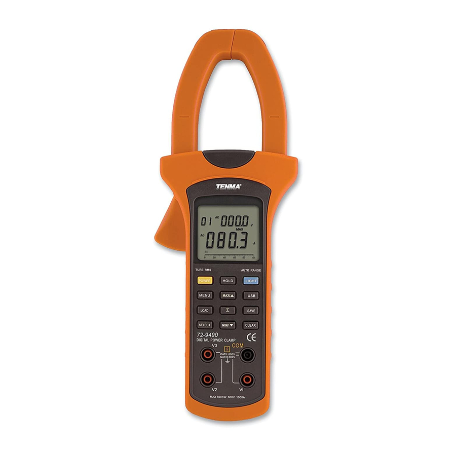
- Page 1 72-9490...
-
Page 2: Table Of Contents
72-9490: OPERATING MANUAL TABLE OF CONTENTS TITLE PAGE Overview Unpacking Inspection Safety Information Rules For Safe Operation International Electrical Symbols The Meter Structure A.The Meter Front Structure B.The Meter Back and Bottom Structure Functional Buttons Display Symbols Measurement Operation A. AC Voltage + Frequency Measurement B. - Page 3 72-9490: OPERATING MANUAL TABLE OF CONTENTS TITLE PAGE A. General Specifications B. Environmental Requirements Accuracy Specifications A. AC Voltage B. Frequency C. AC Current D. Active Power E. Apparent Power F. Reactive Power G. Power Factor H. Phase Angle I. Active Energy Maintenance A.
-
Page 4: Overview
To avoid electric shock or personal injury, read the “Safety Information” and “Rules for Safe Operation” carefully before using the Meter. Model 72-9490 is a three phase intelligent handheld digital power clamp meter (hereafter referred to as “the Meter”) which has both the features of digital current meter and also power measurement meter. -
Page 5: Unpacking Inspection
72-9490: OPERATING MANUAL Unpacking Inspection Open the carton and remove the Meter. Check the following items carefully to see if any items are missing or damaged. Item Description English Operating Manual 1 piece Red Test Lead 1 piece Black Test Lead... -
Page 6: Safety Information
72-9490: OPERATING MANUAL Safety Information This Meter complies with the Safety/ Compliances: IEC 61010 CAT. III 600V, CAT. IV 300V overvoltage and double insulation standard, pollution degree 2. CAT. III: Distribution level, fixed installation, with smaller transient overvoltages than CAT. IV CAT.IV: Primary supply level, overhead lines, cable systems etc. -
Page 7: Rules For Safe Operation
72-9490: OPERATING MANUAL Rules For Safe Operation Warning To avoid possible electric shock or personal injury, and to avoid possible damage to the Meter or to the equipment under test, adhere to the following rules: Before using the Meter, inspect the case. Do not use the Meter if it is damaged or the case (or part of the ... - Page 8 72-9490: OPERATING MANUAL When opening the battery door, make sure the Meter is off. When servicing the Meter, use only the same model number or identical electrical specifications replacement parts. Do not tamper with the internal circuits of the Meter.
-
Page 9: International Electrical Symbols
72-9490: OPERATING MANUAL International Electrical Symbols AC (Alternating Current) Grounding Double Insulated Warning. Refer to the Operating Manual Deficiency of Built-In Battery Danger of High Voltage Conforms to Standards of European Union... -
Page 10: The Meter Structure
72-9490: OPERATING MANUAL The Meter Structure Transformer Jaw: designed to pick up the AC and DC current flowing through the conductor. A. The Meter Front Structure (see figure 1) The tested conductor must vertically go through the Jaw center. Hand Guards. - Page 11 72-9490: OPERATING MANUAL Sigma button (Sum) SAVE button (data store button) USB button LIGHT button (auto display backlight button) HOLD button LCD Display Testing Leads (Red, Black, Blue and Yellow)
-
Page 12: B.the Meter Back And Bottom Structure
72-9490: OPERATING MANUAL B. The Meter Back and Bottom Structure (see figure 2) Figure 2 Infrared slot USB Interface Cable... -
Page 13: Functional Buttons
72-9490: OPERATING MANUAL Functional Buttons The table below describes the function of the main button operations. Button Operation Performed POWER Press and hold POWER for 1 second to turn the Meter on. Press POWER again to turn the Meter off. - Page 14 72-9490: OPERATING MANUAL Button Operation Performed Press USB once to turn the USB interface on, USB appears and the Meter beeps. Press USB again to turn the USB interface off, USB disappears and the Meter beeps. LOAD Press once to enter LOAD mode, MR appears and the Meter beeps.
- Page 15 72-9490: OPERATING MANUAL Button Operation Performed MIN / Press to start recording of minimum value, it valid at voltage, current, active power and apparent power ranges only. Press once at LOAD mode, MR icon shown, the Meter displays the next stored reading, the left secondary display showing the index decrease one.
-
Page 16: Display Symbols
72-9490: OPERATING MANUAL Display Symbols Number Symbol Meaning (see figure 3) Data is transferring via USB Indicator for DC measurement First phase symbol Second phase symbol Third phase symbol Unit for hour Unit for minute Watt: Sum of Watt The battery is low. - Page 17 72-9490: OPERATING MANUAL Number Symbol Meaning Minimum reading Analog Bar Graph Overloading Ruler Maximum reading Indicator for clear the stored reading Ruler negative symbol High voltage symbol Indicates negative reading Indicator for AC voltage or current Indicator for recall the stored reading...
-
Page 18: Measurement Operation
72-9490: OPERATING MANUAL Measurement Operation Starting Your Meter Press and hold POWER for one second to turn the Meter on. The default range is the last measurement range when you turned off the Meter. Replace the battery as soon as the battery indicator “... - Page 19 72-9490: OPERATING MANUAL The AC Voltage ranges are:15V, 100V, 300V and 600V The frequency range is:20Hz~500Hz To measure AC voltage + frequency, connect the Meter as follows: 1. Insert the red test lead into the V1 terminal, blue test lead into the V2 terminal, yellow test lead to V3 input terminal and black test lead to the COM input terminal.
-
Page 20: Ac Current + Ac Voltage Measurement
72-9490: OPERATING MANUAL B. AC Current (main display) + AC Voltage The AC current ranges are: 40A, 100A, 400A and 1000A (secondary display) Measurement (see figure 5) The AC Voltage ranges are: 15V, 100V, 300V and 600V To measure AC current + AC voltage, connect the Meter as follows: 1. -
Page 21: Active Power + Phase Angle Measurement
72-9490: OPERATING MANUAL 6. Press MIN/ , the LCD displays MAX, it starts recording the minimum AC current True RMS value. Press MIN/ , again to show the present AC current True RMS value. 7. The display shows OL when the current of the tested conductor is higher than 1000A rms. - Page 22 72-9490: OPERATING MANUAL When measuring 3 phase 4 wires, connect the Insert red test leads to V1 input terminal. Meter as shown in figure 6 Insert blue test leads to V2 input terminal Insert yellow test leads to V3 input terminal and connect each lead to the corresponding live wire of the 3 phase.
- Page 23 72-9490: OPERATING MANUAL 1)When measuring 3 phase 3 wires, connect the Meter as shown in figure 7 Blue Yellow yellow phase’s...
- Page 24 72-9490: OPERATING MANUAL...
- Page 25 72-9490: OPERATING MANUAL as shown in figure 8 neutral...
- Page 26 72-9490: OPERATING MANUAL 4. When measuring 3 phases 4 wires: After summing up the current power measurement (see figure 9, 10, 11, 12, 13, 14, 15, 16) valueof the first phase, then press SELECT to choose phase 2 as shown in figure 11.
- Page 27 72-9490: OPERATING MANUAL After summing up the current power measurement value After summing up the current power measurement of the second phase, then press SELECT again to value of the third phase, finally press SELECT again choose tphase 3 as shown in figure 13.
- Page 28 72-9490: OPERATING MANUAL 5. When measuring 3 phase 3 wires: The first and second phase measuring method is same as 3 phase 4 wires. Jump over the third phase measurement. Press SELECT to display the 3 phase sum of active power and reactive power.
-
Page 29: Apparent Power + Reactive Power Measurement
72-9490: OPERATING MANUAL D. Apparent Power (main display) + Reactive Power (secondary display) Measurement Warning To avoid damage to the Meter or personal injury, do not exceed AC voltages of 600V rms and AC Current of 1000A rms. To test for Apparent power (main display) + Reactive power (secondary display), connect the Meter as follows: 1. - Page 30 72-9490: OPERATING MANUAL The double display shows the second phase value of apparent power kVA and reactive power Kvar. Press SELECT again to choose the third phase 3, see figure 19. Figure 19 The double display shows the third phase value of apparent power kVA and reactive power Kvar.
-
Page 31: Power Factor + Phase Angle Measurement
72-9490: OPERATING MANUAL E. Power Factor (main display) + Phase Angle (secondary display) Measurement Warning To avoid damage to the Meter or personal injury, do not exceed AC voltages of 600V rms and AC Current of 1000A rms. To test for Power factor (main display) + Phase angle (secondary display), connect the Meter as follows: 1. - Page 32 72-9490: OPERATING MANUAL The double display shows the second phase value of power factor PF and phase angle PG. Press SELECT again to choose the third phase 3, see figure 22. Figure 22 The double display shows the third phase value of power factor PF and phase angle PG.
-
Page 33: Active Energy + Time Measurement
72-9490: OPERATING MANUAL F. Active Energy (main display) + Time (secondary display) Measurement Warning To avoid damage to the Meter or personal injury, do not exceed AC voltages of 600V rms and AC Current of 1000A rms. To test for Active Energy (main display) + Time (secondary display), connect the Meter as follows: 1. -
Page 34: True Rms Measurement And Average Value Measurement
72-9490: OPERATING MANUAL The maximum reading of acitve energy is 9999kWh. OL will be displayed when the reading is over than that. 5. MAX/ and MIN/ are not valid when measuring active energy. 6. Press CLEAR to reset the time. - Page 35 72-9490: OPERATING MANUAL Input Waveform PK-PK 0-PK Sine waveform 2.828 1.414 1.000 0.900 PK-PK complete sine waveform 1.414 1.414 1.000 0.900 PK-PK Half wine waveform 2.828 2.828 1.414 0.900 PK-PK square waveform 1.800 0.900 0.900 0.900 PK-PK commutate square waveform 1.800...
-
Page 36: Specifications
72-9490: OPERATING MANUAL Specifications A. General Specifications Maximum Voltage between any Terminal and grounding: Refer to different range input protection voltage. Display: Multi LCD displays, Maximum display 9999. Ranges: Auto Overloading: Display OL. Battery Deficiency: Display Data Holding: Display Data Logging: Maximum 99, Single or Continuous records... -
Page 37: Environmental Requirements
72-9490: OPERATING MANUAL B. Environmental Requirements The Meter is suitable for indoor use. Altitude: Operating: 2000m Storage: 10000m Temperature and humidity: Operating: ~ 30 ( 85%R.H) ~ 40 ( 75%R.H) ~ 50 ( 45%R.H) Storage: ~ +60 ( 85%R.H) Safety/ Compliances: IEC 61010 CAT. III 600V, CAT. IV 300V overvoltage and double insulation standard, pollution degree 2. -
Page 38: Accuracy Specifications
72-9490: OPERATING MANUAL Accurate Specifications Accuracy: (a% reading + b digits), guaranteed for 1 year. Operating temperature: 23 Operating humidity: 45~75%R.H A. AC Voltage (True RMS) Range Resolution Accuracy Allowable Maximum overload protection voltage Input Impedance 100V 0.1V (1.2%+5) 600 RMS... -
Page 39: Active Power
72-9490: OPERATING MANUAL D. Active Power ( W=V x A x COS Voltages Range Current / Voltage 100V 300V 600V 0.60kW 4.00kW 12.00kW 24.00kW Current 100A 1.50kW 10.00kW 30.00kW 60.00kW Range 400A 6.00kW 40.00kW 120.0kW 240.0kW 1000A 15.00kW 100.0kW 300.0kW 600.0kW... -
Page 40: Apparent Power
72-9490: OPERATING MANUAL E. Apparent Power (VA = V x A) Voltages Range Current / Voltage 100V 300V 600V 0.60kVA 4.00kVA 12.00kVA 24.00kVA Current 100A 1.50kVA 10.00kVA 30.00kVA 60.00kVA Range 400A 6.00kVA 40.00kVA 120.0kVA 240.0kVA 1000A 15.00kVA 100.0kVA 300.0kVA 600.0kVA... -
Page 41: Reactive Power
72-9490: OPERATING MANUAL F. Reactive Power (Var = V x A x SIN Voltages Range Current / Voltage 100V 300V 600V 0.60kVar 4.00kVar 12.00kVar 24.00kVar 100A 1.50kVar 10.00kVar 30.00kVar 60.00kVar Current 400A 6.00kVar 40.00kVar 120.0kVar 240.0kVar Range 1000A 15.00kVar 100.0kVar 300.0kVar... -
Page 42: Phase Angle
72-9490: OPERATING MANUAL H. Phase Angle (PG=acos (PF)) Range Accuracy Resolution Measuring Condition The minimum measuring current 10A 0° ~360° 1° 1° The minimum measuring voltage 45V Measuring current less than 10A OR 0° ~360° For reference only Measuring voltage less than 45V... -
Page 43: Maintenance
72-9490: OPERATING MANUAL MAINTENANCE This section provides basic maintenance information including battery replacement instruction. Warning Do not attempt to repair or service your Meter unless you are qualified to do so and have the relevant calibration, performance test, and service information. -
Page 44: Replacing The Battery
72-9490: OPERATING MANUAL B. Replacing the Battery (see figure 24) Warning To avoid false readings, which could lead to possible electric shock or personal injury, replace the battery as soon as the battery indicator “ ” appears. Make sure the transformer jaw and the tests leads are disconnected from the circuit being tested before opening the case bottom. - Page 45 72-9490: OPERATING MANUAL This operating manual is subject to change without notice Copyright 2012 All rights reserved. Manufacturer: Tenma Test Equipment 405 S. Pioneer Blvd. Springboro, OH 45066 http://www.tenma.com...
Need help?
Do you have a question about the 72-9490 and is the answer not in the manual?
Questions and answers