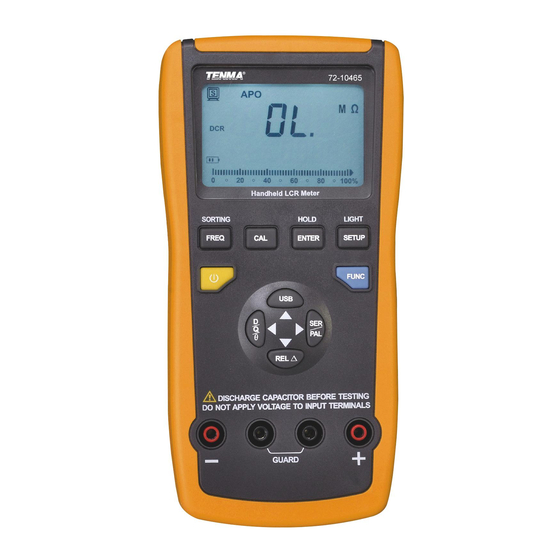
Summary of Contents for Tenma 72-10465
-
Page 1: Operating Manual
Operating Manual 72-10465 LCR Meter www.element14.com www.farnell.com www.newark.com www.cpc.co.uk Page <1> 10/01/18 V1.0... -
Page 2: Table Of Contents
LCD Display Instructions (shown in Figure 2) ..5 VII. Instructions of key functions of 72-10465 front panel (Shown in Figure 3) ..... . . 6 VIII. -
Page 3: General Characteristics And Safety Notice
I. General Characteristics and Safety Notice The 72-10465 LCR meter features an easy to read dual display measurement of 19999/1999. It also has serial and parallel measurement modes which can be used to select quality factor, loss factor, phase location angle, and equivalent resistance of measure articles. -
Page 4: Impedance Parameters
DC impedance, while a bridging instrument (such as this) can be used to measure AC or DC imped- ance. The 72-10465 is an intelligent double-display portable LCR digital electric bridge, with DC & AC impedance measure- ment functions. -
Page 5: Lcd Display Instructions (Shown In Figure 2)
Impedance under serial link mode Rs: Serial mode of resistance Xa: Serial mode of reaction Cs: Serial mode of capacitance Ls: Serial mode of inductance Admittance parallel mode Rp: Parallel mode of resistance XP: Reaction under parallel mode CP: Parallel mode of capacitance LP: Parallel mode of inductance VI. -
Page 6: Instructions Of Key Functions Of 72-10465 Front Panel (Shown In Figure 3)
13) EPR: Equivalent parallel resistance 14) DUT: Articles to measure 15) Key continuation can be expressed by pressing key for less than 1s or more than 2s. VII. Instructions of key functions of 72-10465 front panel (Shown in Figure 3) (1) LCD display zone... - Page 7 “AUTO LCR” mode. 4. Measurement frequency “1kHz→10kHz→100kHz→100Hz→120Hz→1kHz”. 72-10465 can provide 5 frequency testing points, namely, 100Hz/120Hz/1kHz/10kHz/100kHz. Bootstrap default frequency is 1K and user can press “FREQ” key to select different frequency points for measurement of “1KHz→10kHz→ 100kHz→100Hz→120Hz→1kHz”. Note: DC impedance is measured under “AUTO DCR” mode and measurement frequency also can be neglected.
- Page 8 7. Calibration function Calibration function can be used to reduce interference of distribution parameters brought in by testing wires effectively. Calibration function includes short-circuit calibration and open circuit calibration. Short-circuit calibration can be adopted to reduce influence of contact resistance and testing wire resistance to measure low-impedance elements. Open circuit calibration also can be adopted to reduce influence of distributed capacitance and distributed resistance of testing wires to measure high-impedance elements.
-
Page 9: Fast Application Guideline
It refers to calibration failure. Check if testing terminals have been inserted into short-circuit pieces or not to guarantee normal short-circuit re-calibration. 8. PC communication Press “PC” key to enter into communication function for “ ” display on LCD. Insert USB wire and start software of PC end upper host for data transmission. - Page 10 3. Capacitors must be discharged completely before measurement. 1 ) Press “ ” for power on. 2) Press “FUNC” to display “Cp” on LCD and select capacitance measurement gear. 3) Insert capacitance into testing port or connect corresponding fittings to measured capacitance (shown in Figure 11). 4) To press “FREQ”...
-
Page 11: Pc Communication Protocol
5. Measurement of DC impedance 1) Press “ ” for power on. 2) Press “FUNC” to display “DCR” on LCD and select measurement gear of DC resistance. 3) Insert resistance into testing port or connect corresponding fittings to measured resistance (shown in Figure 13). Note: Auxiliary parameter and measurement frequency of DC resistance will be neglected and auxiliary parameter will not be displayed on LCD. - Page 12 Measurement The Min. Precision ±(a% of reading + b of word Function Frequency Range mode Resolution quantity) (under 18°C to 28°C) 20mH 1μH 1%+5 200mH 0.01mH 0.5%+5 2000mH 0.1mH 0.5%+5 100Hz/120Hz 0.5%+5 200H 0.01H 1%+5 2000H 0.1H 1%+5 20kH 0.001kH 2%+5 2000μH 0.1μH...
- Page 13 Measurement The Min. Precision ±(a% of reading + b of word Function Frequency Range mode Resolution quantity) (under 18°C to 28°C) 20μF 0.5%+5 1kHz 200μF 0.01uF 1%+5 2000μF 1%+5 200pF 0.01pF 2%+5 2000pF 0.1pF 1%+5 10kHz 20nF 1%+5 Capacitance Cs/Cp 200nF 0.01nF 1.5%+5...
-
Page 14: Battery Replacement
Group was aware of the possibility of such loss or damage arising) is excluded. This will not operate to limit or restrict the Group’s liability for death or personal injury resulting from its negligence. Tenma is the registered trademark of the Group. © Premier Farnell Limited 2016.


Need help?
Do you have a question about the 72-10465 and is the answer not in the manual?
Questions and answers