Table of Contents
Advertisement
Quick Links
Advertisement
Table of Contents

Subscribe to Our Youtube Channel
Related Manuals for Tenma 72-3545


Summary of Contents for Tenma 72-3545
- Page 1 200A True RMS Fork Meter Models: 72-3545...
-
Page 2: Table Of Contents
CONTENTS Page Number Details What’s Included Important Safety Information Product Overview SELECT Button REL Button ZERO Button HOLD Button Backlight Button Torch Button General Specification Environmental Limit Electrical Specification Measuring AC Current Specification Measuring DC Current Specification Measuring AC Voltage Specification Measuring DC Voltage Specification Measuring Resistance Specification Conductivity Testing Specification... -
Page 3: What's Included
WHAT’S INCLUDED • Fork Meter • One pair of probes • One zip bag • One user manual Please read these instructions carefully before use and retain for future reference. IMPORTANT SAFETY INFORMATION • When using electrical appliances basic safety precautions should always be followed. -
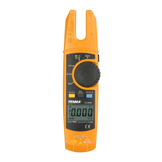
Page 4: Product Overview
PRODUCT OVERVIEW 1. Clamp head - the sensing device for AC/DC measurement. Fix the wire into the designated position to measure the current through the wire. As the head may touch the live wire at the time of the measurement, keep your hand below the clamp head. 2. -
Page 5: Zero Button
entered relative value measuring mode. • You can return to normal operation mode by pressing the REL button again, or pressing SELECT for a function switch. • Press the HOLD button under relative value measuring mode and it will enter data- hold mode as well and the Meter will not update the measurement data. -
Page 6: Torch Button
TORCH BUTTON • To switch on the LED light ensure the Meter is on and simply press the torch button on the side of the Meter. • Press the same button to turn off the light. GENERAL SPECIFICATION Max. display 5999 Polarity display Automatic positive and negative Overload display... -
Page 7: Electrical Specification
ELECTRICAL SPECIFICATION Accuracy ± (% reading + word count), calibration period is one year Ambient temperature 23°C ± 5°C Ambient humidity ≤80%RH Temperature coefficient 0.1 x (accuracy)/°C AC CURRENT SPECIFICATION Measurement range Resolution ratio Accuracy Overload protection 200.0A 0.1A ±(2.5% + 5) 200A •... -
Page 8: Conductivity Testing Specification
RESISTANCE SPECIFICATION Measurement range Resolution ratio Accuracy Overload protection 600.0Ω 0.1Ω ±(1.2% + 2) 6.000KΩ 0.001kΩ 60.00KΩ 0.01kΩ ±(1.0% + 2) 1000V DC / 750V AC 600.0KΩ 0.1kΩ 6.000MΩ 0.001MΩ ±(1.2% + 2) 60.00MΩ 0.01MΩ ±(1.5% + 5) CONDUCTIVITY TESTING SPECIFICATION Measurement Resolution Overload... -
Page 9: Measurement Operations - Measuring Ac Current
MEASUREMENT OPERATIONS - MEASURING AC CURRENT • Set the measuring function range of AC current by rotating the dial to A . The meter will be within the measuring function range of AC current as default. • Clamp the instrument to the input current signal to be tested. -
Page 10: Measuring Ac Voltage
MEASURING AC VOLTAGE • Insert the black probe into the “COM” input and the red probe into the “V Ω” input. • Set the measuring function range of AC voltage by rotating the dial to V • The Meter will be within the measuring function range of AC voltage as default. -
Page 11: Measuring Resistance
MEASURING RESISTANCE • Insert the black probe into the “COM” input and the red probe into the “V Ω” input, ready for measurement. • Set the measuring function range to Resistance by rotating the dial to the “Ω” symbol. • Place the two probes across the circuit elements to be tested. -
Page 12: Diode Measurement
DIODE MEASUREMENT • Insert the black probe into the “COM” input and the red probe into the “V Ω” input, ready for measurement. • Set the measuring function range by rotating the dial so it aims at the “ ” symbol. •... -
Page 13: Measuring Induced Voltage (Ncv)
MEASURING INDUCED VOLTAGE (NCV) • Set the measuring function range by rotating the dial so it aims at “NCV”. • The top right end of the clamp head is equipped with an electromagnetic induction sensor, which is able to detect whether the alternating current magnetic field exists or not. - Page 14 INFORMATION ON WASTE DISPOSAL FOR CONSUMERS OF ELECTRICAL & ELECTRONIC EQUIPMENT. When this product has reached the end of its life it must be treated as Waste Electrical & Electronic Equipment (WEEE). Any WEEE marked products must not be mixed with general household waste, but kept separate for the treatment, recovery and recycling of the materials used.
Need help?
Do you have a question about the 72-3545 and is the answer not in the manual?
Questions and answers