
Related Manuals for Tenma 72-7222


Summary of Contents for Tenma 72-7222
-
Page 1: Table Of Contents
Model 72-7222: OPERATING MANUAL Table of Contents Title Page Overview Inspection Safety Information Rules For Safe Operation International Electrical Symbols The Meter Structure Rotary Switch Function Buttons Function Button Use Display Symbols Measurement Operation A. DC Voltage Measurement B. AC Voltage Measurement C. - Page 2 Model 72-7222: OPERATING MANUAL...
-
Page 3: Overview
To avoid electric shock or personal injury, read the “Safety Information” and “Rules for Safe Operation” carefully before using the Meter. The Digital Clamp Multimeter Model #72-7222 (hereafter referred to as “the Meter”) is 3 1/2 digits with precise operation, fashionable structure and highly reliable measuring instrument. -
Page 4: Inspection
Model 72-7222: OPERATING MANUAL Inspection Open the package case and take out the Meter. Check the following items carefully to see if any items are missing or damaged. Item Description 1 piece English Operating Manual 1 pair Test Lead Point Contact Temperature Probe 1 piece 1.5V Battery (AAA) -
Page 5: Safety Information
Model 72-7222: OPERATING MANUAL Safety Information This Meter complies with the standards IEC61010: in pollution degree 2, overvoltage category (CAT. II 600V, CAT. III 300V) and double insulation. CAT. II: Local level, appliance, PORTABLE EQUIPMENT etc., with smaller transient overvoltages than CAT. III. -
Page 6: Rules For Safe Operation
Model 72-7222: OPERATING MANUAL Rules For Safe Operation (1) Warning To avoid possible electric shock or personal injury, and to avoid possible damage to the Meter or to the equipment under test, adhere to the following rules: l Before using the Meter inspect the case. Do not use the Meter if it is damaged or the case (or part of the case) is removed. - Page 7 Model 72-7222: OPERATING MANUAL Rules For Safe Operation (2) l When working at an effective voltage over 60VDC or 30VAC RMS, special care should be taken for there is danger of electric shock. l Use the proper terminals, function, and range for your measurements.
-
Page 8: International Electrical Symbols
Model 72-7222: OPERATING MANUAL International Electrical Symbols AC (Alternating Current). DC (Direct Current). AC or DC. Ground. Double Insulated. Low Battery Continuity Test. Diode. Capacitance Test Fuse. Warning. Refer to the Operating Manual. Conforms to Standards of European Union. -
Page 9: The Meter Structure
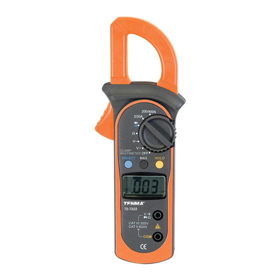
Model 72-7222: OPERATING MANUAL The Meter Structure (see figure 1) ( figure 1) Input Terminals LCD Display Function Buttons Rotary Switch Trigger: press the lever to open the transformer jaws. When the pressure on the lever is released, the jaws will close. -
Page 10: Rotary Switch
Model 72-7222: OPERATING MANUAL Rotary Switch The following table provides information regarding the Rotary Switch positions. Rotary Function Switch Position Power is turned off. AC/DC voltage measurement. : Diode test. : Continuity test. Ω Ω : Resistance measurement. Temperature measurement AC current measurement range from 0.001A... -
Page 11: Function Buttons
Model 72-7222: OPERATING MANUAL Function Buttons(1) The following table provides information regarding function button operations. voltage measurement. l Press HOLD to enter and exit the HOLD Hold mode in any mode, the Meter beeps. l Press and hold HOLD button while turning on the Meter to display full icons. -
Page 12: Function Button Use
Model 72-7222: OPERATING MANUAL The Effectiveness of Function Button Use Not every function button is used in every rotary switch position. The table below indicates which button can be used in which switch position. Rotary Switch Function Button Position SELECT HOLD Ω... -
Page 13: Display Symbols
Model 72-7222: OPERATING MANUAL Display Symbols(1) (see figure 2) Symbol Meaning Indicator for AC voltage or current Indicator for DC voltage Low battery. Warning: To avoid false readings, which could lead to possible electric shock or personal injury, replace the battery as soon as the battery indicator appears. - Page 14 Model 72-7222: OPERATING MANUAL Display Symbols(2) (see figure 2) Symbol Meaning Amperes (amps). The unit of current. mV, V Volts. The unit of voltage.mV: Millivolt. 1x10 or 0.001 volts Indicates negative reading The input value is too large for the...
-
Page 15: Measurement Operation
Model 72-7222: OPERATING MANUAL Measurement Operation(1) A. DC Voltage Measurement (see figure 3) black ( figure 3) Warning To avoid damage to the meter, or risk of personal injury, do not attempt to measure higher than 600V AC/DC, although readings may be obtained. -
Page 16: Ac Voltage Measurement
Model 72-7222: OPERATING MANUAL Measurement Operation(2) When DC voltage measurement has been completed, disconnect the test leads from the circuit under test, and remove them from the input terminals. B. AC Voltage Measurement (see figure 4) black ( figure 4) -
Page 17: Measuring Resistance
Model 72-7222: OPERATING MANUAL Measurement Operation(3) Note l In each range, the Meter has an input impedance of 10MΩ. This loading effect can cause measurement errors in high impedance circuits. If the circuit impedance is less than or equal to 10kΩ, the error is negligible (0.1 or less). - Page 18 Model 72-7222: OPERATING MANUAL Measurement Operation(4) The resistance ranges are: 200.0 , 2.000k , 20.00k ,200k ,2.000M and 20.00M . To measure resistance, connect the Meter as follows: 1. Insert the red test lead into the terminal and the black test lead into the COM terminal.
-
Page 19: Testing Diodes
Model 72-7222: OPERATING MANUAL Measurement Operation(5) D.Testing Diodes (see figure 6) black Warning To avoid damage to the Meter or to the devices under test, disconnect circuit power and discharge all the high-voltage capacitors before testing diodes. Use the diode test to check diodes, transistors, and other semiconductor devices. -
Page 20: Testing For Continuity
Model 72-7222: OPERATING MANUAL Measurement Operation(6) Note l In a circuit, a good diode should still produce a forward voltage drop reading of 0.5V to 0.8; however, the reverse voltage drop reading can vary depending on the resistance of other pathways between the probe tips. - Page 21 Model 72-7222: OPERATING MANUAL Measurement Operation(7) Warning To avoid damages to the Meter or to the devices under test, disconnect circuit power and discharge all the high-voltage capacitors before measuring continuity. To test for continuity, connect the Meter as follows: 1.
-
Page 22: Temperature Measurement
Model 72-7222: OPERATING MANUAL Measurement Operation(8) Temperature Measurement (see figure 8) black The temperature measurement ranges are -40 C~1000 and -40 F~1832 To measure temperature, connect the Meter as follows: 1. Insert the red temperature probe into the VΩ terminal and the black temperature probe into the COM terminal. -
Page 23: Ac Current Measurement
Model 72-7222: OPERATING MANUAL Measurement Operation(9) G. AC Current Measurement (see figure 9) Warning To avoid electric shock, never measure current while the test leads are inserted into the input terminals. Never attempt an in-circuit current measuremnet where the open-circuit voltage between the circuit and the ground is greater than 600V Use proper function and range for the measurement. - Page 24 Model 72-7222: OPERATING MANUAL Measurement Operation(10) Note: l To obtain accurate reading, measure only one conductor at each time. l When current measurement has been completed, press the lever to open the transformer jaw again and remove the jaw from the conductor under test.
-
Page 25: Sleep Mode
Model 72-7222: OPERATING MANUAL Sleep Mode To preserve battery life, the Meter automatically turns off after 15 minutes of inactivity. The Meter can be activated by turning the rotary switch or pressing any button with the following conditions: 1) If the meter enters sleep mode while in the temperature function, the meter cannot be activated by turning the rotary switch to an AC current range. -
Page 26: Specifications
Model 72-7222: OPERATING MANUAL Specifications A. General Specifications: l Maximum voltage including transient overvoltage between any terminals and ground: 500V rms. l Display: 3 1/2 digits LCD display, Maximum display 1999 l Auto Polarity Display l Overload : Display OL or –OL... -
Page 27: Accuracy Specifications
Model 72-7222: OPERATING MANUAL Accuracy Specifications(1) Accuracy: (a% reading + b digits), guarantee for 1 year. Operating temperature: 23 Relative humidity: 75%R.H Temperature coefficient: 0.1x(specified accuracy)/1 A. AC Voltage: Auto ranging Overload Accuracy Range Resolution Protection 2.000V (1.2%+5) 20.00V 10mV 600V rms 200.0V... -
Page 28: Resistance
Model 72-7222: OPERATING MANUAL Accuracy Specifications(2) C. Resistance: Auto ranging Overload Accuracy Range Resolution Protection (1.2%+2) 200.0Ω 100mΩ 2.000kΩ 1Ω (1%+2) 20.00kΩ 10Ω 600Vp 200.0kΩ 100Ω 2.000MΩ 1kΩ (1.2%+2) (1.5%+2) 20.00MΩ 10kΩ Remarks: Input impedance: 10MΩ . D. Continuity Test... -
Page 29: Temperature
Model 72-7222: OPERATING MANUAL Accuracy Specifications(3) F. Temperature: Overload Range Resolution Accuracy Protection -40~0 (3%+9) 0~400 -40~1000 (1%+7) 400~1000 (2%+10) 600Vp -40~32 (3%+10) F~1832 F~752 (1%+8) F~1832 (2%+18) G. AC Current: Auto ranging Overload Frequency Range Resolution Accuracy Protection Response (4%+30) 1A 2.000A... -
Page 30: Maintenance
Model 72-7222: OPERATING MANUAL MAINTENANCE(1) This section provides basic maintenance information including battery replacement instruction. Warning Do not attempt to repair or service your Meter unless you are qualified to do so and have the relevant calibration, performance test, and service information. - Page 31 Model 72-7222: OPERATING MANUAL MAINTENANCE(2) Warning To avoid false readings, which could lead to possible electric shock or personal injury, replace the battery as soon as the battery indicator “ ” appears. Make sure the transformer jaw and the tets leads are disconected from the circuit being tested before opening the case bottom.
- Page 32 Model 72-7222: OPERATING MANUAL Copyright 2006 Tenma Test Equipment. All rights reserved. Tenma Test Equipment 405 S. Pioneer Blvd. Springboro,Ohio 45066 www.tenma.com...
Need help?
Do you have a question about the 72-7222 and is the answer not in the manual?
Questions and answers