Table of Contents
Advertisement
Quick Links
Advertisement
Table of Contents

Related Manuals for Tenma 72-8150


Summary of Contents for Tenma 72-8150
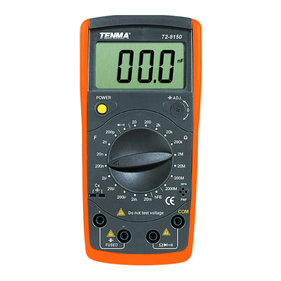
- Page 1 Pocket Size Digital Multimeter Models: 72-8150 and 72-8155...
-
Page 2: Important Safety Information
Description Power Press once to turn the meter on / press again to turn the meter off Press DOWN to enter capacitance measurement. (72-8155) Press UP to enter inductance measurement. Zero cap Press to adjust small capacitance to zero. (72-8150) - Page 3 LCD display L-C switch / zero capacitance adjustment switch Transistor jack. Resistance, diode and continuiyty terminal. Capacitance and inductance terminal. Range selector. Power. RANGE SELECTOR FUNCTIONS AND DISPLAY Symbol Meaning Data hold is active. The battery is low. ß Transistor test. Diode test.
-
Page 4: Operation
OPERATION Measuring Resistance. • To measure voltage, do the following: Ω Insert the red test clip into the terminal and the black test clip into COM terminal. Ω Set the range selector to Ω Ω Ω • The resistance ranges are 20 , 200 , 2k Ω... - Page 5 Measuring Diode. Use the diode test to check diodes, transistors, and other semiconductor devices. The diode test sends a current through the semiconductor junction, and then measures the voltage drop across the junction. Note: A good silicon junction drops between 500mV and 800mV. •...
- Page 6 When measuring small value capacitor, that is 200pF, 2nF and 20nF, first open circuit the test clips or the Small Value Capacitance Jack, then turn the Capacitance Zero Adjustment Switch to adjust zero (72-8150 model). • The meter displays the measured value.
-
Page 7: Battery And Fuse Replacement
Measuring Inductance (72-8155 only) • To measure inductance, do the following: Set the rotary switch to Lx measurement mode. If the tested inductance value is unknown, use the maximum measurement position and decrease the range step by step until a satisfactory reading is obtained. - Page 8 Replacing the Fuses. Warning: To avoid electrical shock, personal injury or damage to the meter, use specified fuses ONLY in accordance with the following procedure. Turn the meter power off and remove all connections from the terminals. Screw Remove the screw from the battery compartment, and separate the battery compartment from the case bottom.
-
Page 9: Specifications
SPECIFICATIONS Maximum Display 1999. Measurement Speed Updates 2-3 times /second. Polarity Auto. (Display “-“ when negative) Overload Indication Display “1” Range Manual Ranging Capacitance zero adjustment around ±20pF Temperature: Operating C~40oC (32 F ~104 Storage C~50 C (14 F~122 Relative Humidity 75% @ 0 C - 30 50% @ 31 - 40... - Page 10 ACCURACY Accuracy specifications Accuracy: ±(a% reading + b digits), guarantee for 1 year. Operating temperature: 23 C ± 5 Relative humidity: < 75%. Temperature coefficient: 0.1 x (specified accuracy) / 1 Resistance Test Range Resolution Accuracy 200Ω 0.1Ω ±(0.8%+3) 2kΩ 1Ω...
- Page 11 Inductance Test Range Resolution Accuracy Testing Frequency/Current 0.001mH 20mH 0.01mH ±(2%+8) 1kHz/150µA 200mH 0.1mH 0.001H ±(5%+5) 0.01H ±(5%+15) 100Hz/15µA Measure of Inductance: 1H=103mH = 106μH. Overload Protection: 0.315A, 250V, fast type fuse, 5x20 mm Inductance Test Range Resolution Accuracy Testing Frequency/Voltage 2.000nF 0.001nF 20.00nF...
- Page 12 INFORMATION ON WASTE DISPOSAL FOR CONSUMERS OF ELECTRICAL & ELECTRONIC EQUIPMENT These symbols indicate that separate collection of Waste Electrical and Electronic Equipment (WEEE) or waste batteries is required. Do not dispose of these items with general household waste. Separate for the treatment, recovery and recycling of the materials used. Waste batteries can be returned to any waste battery recycling point which are provided by most battery retailers.
Need help?
Do you have a question about the 72-8150 and is the answer not in the manual?
Questions and answers