Advertisement
Quick Links
Download this manual
See also:
Instruction Manual
advanced FLOW engineering
Instruction Manual
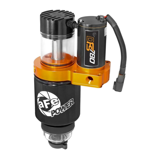
Make: GM Model: Diesel Trucks Year: 2001-2010 Engine: V8-6.6L (td) Duramax
Fuel Pressure: 8-10 PSI (Boost Operated) Supported Horsepower: 2000+
P/N: 42-14012
Advertisement

Subscribe to Our Youtube Channel
Related Manuals for aFe Power dfs780


Summary of Contents for aFe Power dfs780
- Page 1 advanced FLOW engineering Instruction Manual P/N: 42-14012 Make: GM Model: Diesel Trucks Year: 2001-2010 Engine: V8-6.6L (td) Duramax Fuel Pressure: 8-10 PSI (Boost Operated) Supported Horsepower: 2000+...
- Page 2 • Please read the entire instruction manual before proceeding. • Ensure all components listed are present. • Ensure you have all necessary tools before proceeding. • Do not attempt to work on your vehicle when the engine is hot. • Disconnect the negative battery terminal before proceeding. •...
- Page 3 Page 3...
- Page 4 REMOVAL Figure 1 Refer to Figure 1 for Steps 1-3 Step 1: Looking at the driver’s side of the truck, on the inside of the frame rail, you will see two hard lines. These are the fuel supply and return lines for the engine. They are held in place by plastic retainers that are bolted to the frame (shown above).
- Page 5 INSTALL Figure 2 Refer to Figure 2 for Steps 4-7 Step 4: Gently pull the fuel lines off of the frame rail. Please be careful not to bend or kink the fuel lines. Step 5: Place the supplied bracket between the frame and the stock fuel line retainer located in Step 2. Step 6: While making sure the bracket is sitting on the bottom of the frame, tighten the stock fuel line retainer.
- Page 6 INSTALL Rear of truck Figure 3 NOTE: This is what the bracket looks like when installed correctly. Page 6...
- Page 7 INSTALL Figure 4 Refer to Figure 4 for Steps 8-9 Step 8: Connect the bracket to the manifold using the four (4) supplied M6x1.0 x 50mm bolts, M6 washers, felt washers and M6 flange nuts. The felt washers go between the pump and the bracket.
- Page 8 Refer to Figure 5 for Step 10 Step 10: Turn sight glass to the desired angle and using a 1-1/4" wrench, tighten the center nut under the DFS780 manifold. NOTE: The pump should look like the picture above. Page 8...
- Page 9 INSTALL Figure 6 Refer to Figure 6 for Step 11 Step 11: Using a light oil, lube the gasket on the fuel filter before installation. Attach the supplied water separator bowl onto the supplied fuel filter. Page 9...
- Page 10 INSTALL “AN fitting” side “NPT” side Figure 7 Refer to Figure 7 for Step 12 Step 12: Apply Teflon tape with (PTFE) or Teflon paste with (PTFE) to the 2 x 3/8" NPT to -8 AN fittings. NOTE: Only apply Teflon to the NPT side of the fitting. Page 10...
- Page 11 INSTALL Figure 8 Refer to Figure 8 for Step 13 Step 13: Install the 2 x 3/8" NPT to -8 AN fittings into the DFS780 manifold (as shown above). Page 11...
- Page 12 INSTALL Figure 9 NOTE: If you have a 2001 - 2008 truck and the fittings look like the above picture, you will need a special tool to release the fuel line from the connectors. You can get this tool at your local parts store. Page 12...
- Page 13 INSTALL Figure 10 NOTE: This is what the connections look like on the 2009 – 2010 truck. Page 13...
- Page 14 INSTALL Figure 11 Refer to Figure 11 for Step 14 Step 14: Clean the area around the fuel lines to prevent dirt and debris from going into the lines. NOTE: 2009-2010 model shown in the pictures. Page 14...
- Page 15 INSTALL Figure 12 Refer to Figure 12 for Step 15 Step 15: Disconnect the 1/2" fuel supply line. NOTE: 2009-2010 model shown in the pictures. Page 15...
- Page 16 INSTALL INSTALL Figure 13 Refer to Figure 13 for Step 16 Step 16: Install the male quick disconnect fitting on the supplied fuel inlet hose (silver 90° “AN” fitting- shown below) onto the female side of the stock fuel feed line. NOTE: 2009-2010 model shown in the pictures.
- Page 17 INSTALL 90 ° Female quick disconnect Figure 14 Refer to Figure 14 for Step 17 Step 17: Install the female quick disconnect fitting on the supplied fuel outlet hose (black 90° “AN” fitting - shown below) onto the male side of the stock fuel feed line. NOTE: 2009-2010 model shown in the pictures.
- Page 18 INSTALL Figure 15 Refer to Figure 15 for Step 18 Step 18: Install the supplied inlet fuel line (90° silver “AN” fitting) onto the fuel inlet port of the DFS780. Page 18...
- Page 19 INSTALL Figure 16 Refer to Figure 16 for Step 19 Step 19: Install the supplied outlet fuel line (90° black “AN” fitting) onto the fuel outlet port of the DFS780. Page 19...
- Page 20 INSTALL Center of truck Figure 17 Refer to Figure 17 for Step 20 Step 20: Locate the factory return line. It is located at the front of the fuel tank near the center of the vehicle. NOTE: 2009-2010 model shown in the pictures. Page 20...
- Page 21 INSTALL Figure 18 Refer to Figure 18 for Step 21 Step 21: Disconnect the factory return fuel line. NOTE: 2009-2010 model shown in the pictures. Page 21...
- Page 22 INSTALL Figure 19 Refer to Figure 19 for Step 22 Step 22: Install the new return line onto the female side by pushing the new male quick disconnect fitting into the factory return line. NOTE: 2009-2010 model shown in the pictures. Page 22...
- Page 23 INSTALL Figure 20 Refer to Figure 20 for Step 23 Step 23: Install the other side of the new return line (female connection) onto the factory return line (male connection) (as shown above). NOTE 1: Make sure that the line does not kink while making connections. NOTE 2: 2009-2010 model shown in the pictures.
- Page 24 INSTALL Figur e 21 Refer to Figure 21 for Step 24 Step 24: Install the supplied return line (-4 AN fitting) onto the top of the DFS780. Page 24...
- Page 25 INSTALL Figure 22 Refer to Figure 22 for Step 25 Step 24: Using the supplied nylon cable ties, secure the new hoses (as shown above). NOTE: 2009-2010 model shown in the pictures. Page 25...
- Page 26 INSTALL Figure 23 Refer to Figure 23 for Step 26 Step 26: Using the supplied nylon cable ties, secure the new hoses (as shown above). Page 26...
- Page 27 Step 27: From the inside of the frame, plug the Deutsch connector of the supplied wiring harness into the mating connector on the DFS780. Step 28: Route the supplied wiring harness along the frame towards the front of the vehicle.
- Page 28 REMOVE Remove the 4 Bolts Figure 25 Refer to Figure 25 for Step 30 Step 30: Remove the corner brace in the engine compartment using a 13mm socket and socket driver. Retain the brace and the hardware for re-installation. Page 28...
- Page 29 INSTALL Figure 26 Refer to Figure 26 for Step 31 Step 31: Run the remaining wiring harness along the frame to the engine compartment. Page 29...
- Page 30 INSTALL Figure 27 Refer to Figure 27 for Step 32 Step 31: Connect the red wire ring terminal to the positive side of the battery. NOTE: Check the fuse to make sure it is already installed in the connector. Page 30...
- Page 31 INSTALL Figure 28 Refer to Figure 28 for Step 33 Step 33: Connect the black wire ring terminal to the negative side on the battery. Page 31...
- Page 32 INSTALL Figure 29 Refer to Figure 29 for Step 34 Step 34: Install the supplied pressure sensor into the intake manifold (1/8" NPT). NOTE: This step may require you to drill and tap a 1/8" NPT hole. Use Caution: DO NOT! allow any metal chips to enter the engine. Page 32...
- Page 33 INSTALL Figure 30 Refer to Figure 30 for Step 35 Step 35: Plug the supplied pressure switch harness into the pressure sensor. Page 33...
- Page 34 Step 36: Make sure that all fittings are tight. Install the priming jumper onto the Deutsch connector on the power harness. The DFS780 will turn on. Use the Schrader valve (on top of the DFS780) to release trapped air. The DFS780 should fill the sight glass with fuel and prime the fuel system.
- Page 35 INSTALL Figure 32 Refer to Figure 32 for Steps 38-39 Step 38: Plug the supplied pressure switch harness into the Deutsch connector on the power harness. Step 39: Organize wire harness and secure with the remaining nylon cable ties. Page 35...
- Page 36 INSTALL Figure 33 Refer to Figure 33 for Step 40 Step 40: Installation is now complete. Make sure that all fittings are tight and that fuel is not leaking from any of the connections made while installing. Page 36...
Need help?
Do you have a question about the dfs780 and is the answer not in the manual?
Questions and answers