Sign In
Upload
Manuals
Brands
ETAS Manuals
Computer Hardware
XETK-S21.0B
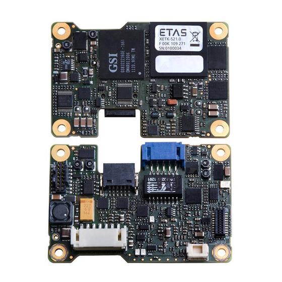
ETAS XETK-S21.0B Manuals
Manuals and User Guides for ETAS XETK-S21.0B. We have
2
ETAS XETK-S21.0B manuals available for free PDF download: User Manual
ETAS XETK-S21.0B User Manual (68 pages)
Emulator Probe for MPC57 and EMU57 MCU Family
Brand:
ETAS
| Category:
Computer Hardware
| Size: 1 MB
Table of Contents
Table of Contents
3
1 About this Manual
7
Identification of Safety Notices
7
Presentation of Information
7
Scope of Supply
8
Additional Information
8
2 Basic Safety Notices
9
General Safety Information
9
Requirements for Users and Duties for Operators
9
Intended Use
9
Identifications on the Product
12
Fig. 2-1 Adhesive Label (Example: Label for XETK-S14.0)
12
Taking the Product Back and Recycling
13
CE Marking
13
Rohs Conformity
13
European Union
13
China
13
Fig. 2-2 WEEE-Symbol
13
Declarable Substances
14
Use of Open Source Software
14
3 Introduction
15
Applications
15
Features
15
Fig. 3-1 XETK-S21.0
15
4 Hardware Description
17
Architecture
17
Fig. 4-1 XETK-S21.0 Architecture
17
ECU Interface
18
Fig. 4-2 Location of the ECU Interfaces
18
XETK Ethernet Interface
19
Fig. 4-3 Location of the XETK Ethernet Interface Connector (CON5)
19
Debug Interface
20
Fig. 4-4 Location of the Debugger Interface (XETK-S21.0)
20
Power Supply
21
ECU Voltage Supervisor
21
Fig. 4-5 Location of the XETK-S21.0 Power Supply Connectors
21
Status Leds
22
Fig. 4-6 Status Leds of the XETK-S21.0
22
Data Emulation and Data Measurement
23
JTAG Interface
24
Fig. 4-7 Equivalent Circuitry of the ECU JTAG Interface (ECU)
24
Trigger Modes: Overview
25
Pinless Triggering
25
Startup Handshake
25
XETK Trigger Generation
25
Timer Triggering
25
Reset
26
Pull Calwakeup until Startup Handshake
26
5 Installation
27
Connection to the ECU
27
Fig. 5-1 XETK-S21.0 Connection to the ECU
27
Fig. 5-2 XETK-S21.0 Connection to the ECU
28
Wiring
29
XETK Ethernet Interface
29
Power Supply
29
Fig. 5-3 Wiring - XETK Ethernet Interface
29
Fig. 5-4 Permanent Power Supply Inside ECU Available
30
Fig. 5-5 Permanent Power Supply Inside ECU Not Available
30
Fig. 5-6 Isolated Power Supply Inside ECU
30
6 XETK Configuration
33
Overview
33
Configuration Parameter
33
7 Technical Data
35
System Requirements
35
ETAS Compatible Hardware
35
PC with One Ethernet Interface
35
Software Support
35
Data Emulation and Measurement Memory
37
Data Emulation Memory and Microcontroller Support
37
Measurement Data Memory
37
Configuration
37
XETK Ethernet Interface
38
Environmental Conditions
38
Power Supply
39
Test Characteristics
40
JTAG Timing Characteristics
40
JTAG Timing Diagram
40
JTAG Timing Parameters
41
Debugger Arbitration Timing Diagram
41
Debugger Arbitration Timing Parameters
41
Electrical Characteristics
42
ECU Interface Characteristics
42
ECU Interface Connector CON6
43
Debugger Interface Connector CON1
43
Pin Assignment
44
ECU Interface Connector CON6
44
Interface and Power Supply Connector CON7
45
Debugger Interface Connector CON1
45
Mechanical Dimensions
46
Fig. 7-1 XETK-S21.0 Dimensions - Top View
46
Fig. 7-2 XETK-S21.0 Dimensions - Side View
46
8 Cables and Accessories
47
ECU Adapter Cable
47
CBAM230 Adapter Cable
47
CBAM240 Adapter Cable
47
Fig. 8-1 CBAM230 Adapter Cable
47
Fig. 8-2 CBAM240 Adapter Cable
47
CBAM271 Adapter Cable
48
Fig. 8-3 CBAM271 Adapter Cable
48
Combined Interface and Power Supply Cable
49
Fig. 8-4 CBAM270 Cable (0.5 M Length)
49
Fig. 8-5 CBAM270 Cable (0.7 M Length)
49
PC Interface Cable
50
CBE200-3 Cable
50
CBAE200 Adapter Cable
50
Fig. 8-6 CBE200-3 Cable
50
Fig. 8-7 CBAE200 Adapter Cable
50
ETAS Module Interface Adapter Cable
51
CBE230 Cable
51
CBAE330 Adapter Cable
51
Fig. 8-8 CBE230 Cable
51
Fig. 8-9 CBAE330 Adapter Cable
51
Power Supply Cables
52
Cable K70
52
Cable KA50
52
Fig. 8-10 Power Supply Cable K70
52
Fig. 8-11 Power Supply Cable KA50
52
ECU Interface Adapters
53
XETK - ECU Adapter ETAI5
53
XETK - ECU Adapter ETAI6
53
Fig. 8-12 XETK - ECU Adapter ETAI5
53
Fig. 8-13 XETK - ECU Adapter ETAI6
53
XETK - ECU Adapter ETAI8
54
XETK - ECU Adapter ETAI10
54
Fig. 8-14 XETK - ECU Adapter ETAI8
54
Fig. 8-15 XETK - ECU Adapter ETAI10
54
Debug Adapter ETAF11
55
Fig. 8-16 ETAF11 Flatcable
55
Fig. 8-17 ETAF11 Component Placement
55
Fig. 8-18 ETAF11 - Mechanical Dimensions and Component Placement
55
Debug Adapter AS_ETAF13.0
56
Fig. 8-19 AS_ETAF13.0 Debug Adapter
56
Water Proof Case ETKS_C3
57
Fig. 8-20 ETKS_C3 Top View
57
Fig. 8-21 ETKS_C3 Bottom View
57
Fig. 8-22 ETKS_C3 Side View
57
9 Ordering Information
59
Xetk-S21.0
59
XETK - ECU Adapter
59
Debug Adapter
59
Power Supply
59
Cables
60
ECU Adapter Cables
60
Combined ECU Adapter and Power Supply Cables
60
Ethernet Cables
61
Power Supply Cables
61
Waterproof Case
62
10 ETAS Contact Addresses
63
Figures
65
Index
67
Advertisement
ETAS XETK-S21.0B User Manual (65 pages)
Emulator Probe for the JDP MPC57xx Microcontroller Family
Brand:
ETAS
| Category:
Computer Hardware
| Size: 3 MB
Table of Contents
Table of Contents
3
About this Document
6
Classification of Safety Messages
6
Presentation of Instructions
6
Typographical Conventions
7
Presentation of Supporting Information
7
Basic Safety Notices
8
General Safety Information
8
Requirements for Users and Duties for Operators
8
Intended Use
8
Identifications on the Product
11
Taking the Product Back and Recycling
12
CE Conformity
12
UKCA Conformity
12
Rohs Conformity
12
Declarable Substances
13
Use of Open Source Software
13
Introduction
14
Applications
14
Features
15
Hardware Description
16
Architecture
16
Fig. 4-1 XETK-S21.0 Architecture
16
ECU Interface
17
Fig. 4-2 Location of the ECU Interfaces
17
XETK Ethernet Interface
18
Fig. 4-3 Location of the XETK Ethernet Interface Connector (CON5)
18
Debug Interface
19
Fig. 4-4 Location of the Debugger Interface (XETK-S21.0)
19
Power Supply
20
Fig. 4-5 Location of the XETK-S21.0 Power Supply Connectors
20
ECU Voltage Supervisor
21
Status Leds
22
Fig. 4-6 Status Leds of the XETK-S21.0
22
Data Emulation and Data Measurement
23
JTAG Interface
24
Fig. 4-7 Equivalent Circuitry of the ECU JTAG Interface (ECU)
24
Trigger Modes: Overview
25
Pinless Triggering
25
Startup Handshake
25
XETK Trigger Generation
25
Timer Triggering
26
Reset
26
Pull Calwakeup until Startup Handshake
26
Installation
27
Connection to the ECU
27
Fig. 5-1 XETK-S21.0 Connection to the ECU
27
Fig. 5-2 XETK-S21.0 Connection to the ECU
28
Wiring
29
XETK Ethernet Interface
29
Fig. 5-3 Wiring - XETK Ethernet Interface
29
Power Supply
30
Fig. 5-4 Permanent Power Supply Inside ECU Available
30
Fig. 5-5 Permanent Power Supply Inside ECU Not Available
30
Fig. 5-6 Isolated Power Supply Inside ECU
30
XETK Configuration
31
Overview
31
Configuration Parameter
31
Technical Data
33
System Requirements
33
ETAS Compatible Hardware
33
PC with One Ethernet Interface
33
Software Support
34
Data Emulation and Measurement Memory
35
Data Emulation Memory and Microcontroller Support
35
Measurement Data Memory
36
Configuration
36
XETK Ethernet Interface
37
Environmental Conditions
37
Power Supply
38
Test Characteristics
39
JTAG Timing Characteristics
39
JTAG Timing Diagram
39
JTAG Timing Parameters
40
Debugger Arbitration Timing Diagram
40
Debugger Arbitration Timing Parameters
40
Electrical Characteristics
41
ECU Interface Characteristics
41
ECU Interface Connector CON6
42
Debugger Interface Connector CON1
43
Pin Assignment
44
ECU Interface Connector CON6
44
Interface and Power Supply Connector CON7
44
Debugger Interface Connector CON1
45
Mechanical Dimensions
46
Fig. 7-1 XETK-S21.0 Dimensions - Top View
46
Fig. 7-2 XETK-S21.0 Dimensions - Side View
46
Cables and Accessories
47
ECU Adapter Cable
47
CBAM230 Adapter Cable
47
CBAM240 Adapter Cable
47
Fig. 8-1 CBAM230 Adapter Cable
47
Fig. 8-2 CBAM240 Adapter Cable
47
CBAM271 Adapter Cable
48
Fig. 8-3 CBAM271 Adapter Cable
48
Combined Interface and Power Supply Cable
49
Fig. 8-4 CBAM270 Cable (0.5 M Length)
49
Fig. 8-5 CBAM270 Cable (0.7 M Length)
49
PC Interface Cable
50
CBE200-3 Cable
50
CBAE200 Adapter Cable
50
Fig. 8-7 CBAE200 Adapter Cable
50
ETAS Module Interface Adapter Cable
51
CBE230 Cable
51
CBAE330 Adapter Cable
51
Fig. 8-9 CBAE330 Adapter Cable
51
Power Supply Cables
52
Cable K70
52
Cable KA50
52
Fig. 8-10 Power Supply Cable K70
52
Fig. 8-11 Power Supply Cable KA50
52
ECU Interface Adapter
53
XETK - ECU Adapter ETAI5
53
XETK - ECU Adapter ETAI6
53
XETK - ECU Adapter ETAI8
53
Fig. 8-12 XETK - ECU Adapter ETAI5
53
Fig. 8-13 XETK - ECU Adapter ETAI6
53
Fig. 8-14 XETK - ECU Adapter ETAI8
53
XETK - ECU Adapter ETAI10
54
Debug Adapter ETAF11
54
Fig. 8-15 XETK - ECU Adapter ETAI10
54
Fig. 8-17 ETAF11 Component Placement
54
Debug Adapter AS_ETAF13.0
55
Fig. 8-18 ETAF11 - Mechanical Dimensions and Component Placement
55
Water Proof Case ETKS_C3
57
Ordering Information
58
Xetk-S21.0
58
XETK - ECU Adapter
58
Debug Adapter
58
Power Supply
58
Cables
59
ECU Adapter Cables
59
Combined ECU Adapter and Power Supply Cables
59
Ethernet Cables
60
Power Supply Cable
60
Waterproof Case
60
Contact Information
61
Figures
62
Index
64
Advertisement
Related Products
ETAS XETK-S4.2
ETAS XETK-S14.0
ETAS XETK-S22.0
ETAS BR XETK-S3.0
ETAS XETK-S31.0
ETAS XETK-S21.0
ETAS BR XETK-S2.0
ETAS XETK-S23.0
ETAS BR XETK-S4.0
ETAS XETK-S20.1B
ETAS Categories
Control Unit
Computer Hardware
Measuring Instruments
Recording Equipment
I/O Systems
More ETAS Manuals
Login
Sign In
OR
Sign in with Facebook
Sign in with Google
Upload manual
Upload from disk
Upload from URL