Table of Contents
Advertisement
Quick Links
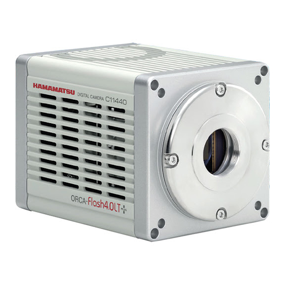
ORCA-Flash4.0 LT+
Digital CMOS Camera
C11440-42U30 / C11440-42U31
Instruction manual
Thank you for your purchase
•
Follow the safety precautions in Chapter 1 in order to avoid personal
injury and damage to property when using this camera. The manual
describes the correct handling method of the camera and provides
instructions that should be followed to avoid accidents. Read this
manual carefully before using this camera. After reading this manual,
store it in a location where you can refer to it at any time.
Ver. 1.2
Feb. 2018
HAMAMATSU PHOTONICS K.K.
A4610301-02
Advertisement
Table of Contents

Related Manuals for Hamamatsu Photonics C11440-42U30


Summary of Contents for Hamamatsu Photonics C11440-42U30
- Page 1 ORCA-Flash4.0 LT+ Digital CMOS Camera C11440-42U30 / C11440-42U31 Instruction manual Thank you for your purchase • Follow the safety precautions in Chapter 1 in order to avoid personal injury and damage to property when using this camera. The manual describes the correct handling method of the camera and provides instructions that should be followed to avoid accidents.
- Page 2 ~ Blank page ~...
-
Page 3: Safety Precautions
C11440-42U30/C11440-42U31 Instruction manual_Ver.1.2 1. SAFETY PRECAUTIONS SYMBOLS The following symbols can be found on this camera: Direct current Alternating current CLASSIFICATION OF WARNINGS We have classified the warnings symbols that appear in this instruction manual and on the camera as follows for your convenience. Make sure that you fully understand them and follow the instructions they contain. -
Page 4: Ac Adapter
C11440-42U30/C11440-42U31 Instruction manual_Ver.1.2 Power supply Use the camera with the indicated voltage on the rating sticker. Using a different voltage can damage the camera and lead to fire or electric shock. Cables Do not to place heavy objects on cables or bend them excessively. Doing so can damage the cables and lead to fire or electric shock. - Page 5 C11440-42U30/C11440-42U31 Instruction manual_Ver.1.2 AC adapter When unplugging the power supply cord, do not pull on the cord. Remove the plug from the outlet to avoid causing electric shock or fire. When unplugging the AC adapter, do not pull on the cord. Remove the plug from the camera to avoid breakdown of the AC adapter or the camera.
-
Page 6: Check The Contents Of Package
When opening the package, check that the following items are included before use. If the contents are incorrect, insufficient, or damaged in any way, contact a Hamamatsu subsidiary or your local distributor before attempting to operate the camera. Camera (C11440-42U30 or C11440-42U31) AC adapter Power supply cord for AC adapter... -
Page 7: Installation
C11440-42U30/C11440-42U31 Instruction manual_Ver.1.2 3. INSTALLATION Avoid using or storing this camera in the following places Places where the temperature is not the operating temperature indicated in the • specifications. Places where the temperature is not the storage temperature indicated in the •... -
Page 8: Table Of Contents
C11440-42U30/C11440-42U31 Instruction manual_Ver.1.2 1. SAFETY PRECAUTIONS ................1 SYMBOLS ......................1 CLASSIFICATION OF WARNINGS ..............1 2. CHECK THE CONTENTS OF PACKAGE ........... 4 3. INSTALLATION ................... 5 4. OVERVIEW ....................8 5. FEATURES ....................8 6. NAME AND FUNCTION OF PARTS ............10 7. - Page 9 C11440-42U30/C11440-42U31 Instruction manual_Ver.1.2 14. DIMENSIONAL OUTLINES ............... 51 14-1 C11440-42U30 for C-mount ................51 14-2 C11440-42U31 for F-mount ................52 15. WARRANTY ....................53 15-1 BASIC WARRANTY .................... 53 15-2 REPAIRS ......................53 16. CONTACT INFORMATION ............... 54...
-
Page 10: Overview
C11440-42U30/C11440-42U31 Instruction manual_Ver.1.2 4. OVERVIEW C11440-42U30/C11440-42U31 is equipped with the new scientific image sensor, an advanced CMOS device that realizes the multiple benefits of high resolution, high readout speed, and low noise all at once. The camera provides 4.0 megapixels resolution at 30 fps (frames/s) (and up to 25 000 fps by sub-array readout) while achieving 0.9 electrons (median) 1.5 electrons (r.m.s) readout noise... - Page 11 C11440-42U30/C11440-42U31 Instruction manual_Ver.1.2 (5) Frame rate The CMOS image sensor realizes both low noise (0.9 electrons (median) 1.5 electrons (r.m.s)) and high speed readout (30 fps with 2048 pixels x 2048 pixels) simultaneously, by a split readout scheme in which the top and the bottom halves of the sensor are readout independently, and the data of each horizontal line is read by 2 lines of column amplifier and A/D in the top and the bottom in parallel and simultaneously.
-
Page 12: Name And Function Of Parts
C11440-42U30/C11440-42U31 Instruction manual_Ver.1.2 6. NAME AND FUNCTION OF PARTS (1) C11440-42U30 for C-mount ③ ④ ② ① ⑧ ⑨ ⑤ ⑥ ⑦ (2) C11440-42U31 for F-mount ② ③ ① ④ ⑧ ⑨ ⑤ ⑥ ⑦ Do not place the rear panel of the camera, which connectors are •... - Page 13 C11440-42U30/C11440-42U31 Instruction manual_Ver.1.2 ① Lens mount C11440-42U30 can be attached to C-mount lens or an optics system. C11440-42U31 can be attached to F-mount lens or an optics system. • The depth of the C-mount is 7 mm. Screwing in the mount too far Note can scratch the glass surface.
- Page 14 C11440-42U30/C11440-42U31 Instruction manual_Ver.1.2 ⑧ Air outlet This is the outlet for the heat ventilation. • To prevent overheating inside the camera, do not wrap the camera in cloth or other material, or block the camera’s ventilation. • If the camera is being operated in an enclosed environment, ensure to keep clearance at least 10 cm from both intake and exhaust vents when setting up.
-
Page 15: Connection
C11440-42U30/C11440-42U31 Instruction manual_Ver.1.2 7. CONNECTION CONNECTING OF CABLES Refer to the figure below when connecting the various cables. Camera(Rear) Computer ②USB 3.0 interface cable USB 3.0 port ①AC adapter Figure 7-1 • When you connect cables, turn off the power supply of the camera and the peripheral devices. -
Page 16: Operations
C11440-42U30/C11440-42U31 Instruction manual_Ver.1.2 8. OPERATIONS OPERATING PRECAUTIONS Be careful of the following when you operate the camera. (1) Cooling method Cooling of this equipment is done using a Peltier element. With a Peltier element, when current is supplied, one surface is cooled, and the other surface is heated. The CMOS image sensor is positioned on the cooling side, and cooling is done by discharging the heat from the heated surface. -
Page 17: Description Of Various Functions
C11440-42U30/C11440-42U31 Instruction manual_Ver.1.2 9. DESCRIPTION OF VARIOUS FUNCTIONS THEORY OF THE CMOS IMAGE SENSOR The pixel of the CMOS image sensor is composed of the photodiode and the amplifier that converts the charge into voltage. Entered light is converted to charge and converted to voltage in the pixel. - Page 18 C11440-42U30/C11440-42U31 Instruction manual_Ver.1.2 The exposure and the readout method of the CMOS image sensor is rolling shutter. In the rolling shutter, the exposure and readout are done line by line. Therefore, the exposure timing is different on one screen. (Figure 9-2) But even if the object moves during the exposure, the affect of rolling shutter is very small.
-
Page 19: Normal Area Mode
C11440-42U30/C11440-42U31 Instruction manual_Ver.1.2 NORMAL AREA MODE 9-2-1 Readout method (Scan mode) With normal area mode, the camera reads out the CMOS image sensor from the center line to the top and from the center line to the bottom simultaneously (center line is depicted in red line in the diagram). -
Page 20: Camera Operation Modes
C11440-42U30/C11440-42U31 Instruction manual_Ver.1.2 9-2-2 Camera operation modes The camera has the following operation modes. (1) Free running mode The camera has the free running mode which the exposure and readout timing can be set by software command and controlled by an internal microprocessor. The free... -
Page 21: Frame Rate Calculation
C11440-42U30/C11440-42U31 Instruction manual_Ver.1.2 9-2-3 Frame rate calculation The calculation formula of frame rate and the value of frame rate are as below. ■ Calculation formula = Number of vertical line (The center of the set area is the middle of the sensor.) Exp1 = 3 ms to 10 s = 32.4812 ×... - Page 22 C11440-42U30/C11440-42U31 Instruction manual_Ver.1.2 ■ Calculation formula (Rapid Rolling Mode) = Number of vertical line (The center of the set area is the middle of the sensor.) Exp1 = 1 ms to 10 s Exp2 = 1.05 ms to 10 s = 10 ×...
- Page 23 C11440-42U30/C11440-42U31 Instruction manual_Ver.1.2 ■ Value of frame rate (Rapid Rolling Mode) (fps) Binning: 1×1 (Normal readout) 2×2 / 4×4 Horizontal 1024 / 1536 Vertical width / 2048 width Free running mode 2048 1024 1562 1562 3125 3125 7692 25 000...
-
Page 24: Configuring Exposure Time
C11440-42U30/C11440-42U31 Instruction manual_Ver.1.2 9-2-4 Configuring exposure time The exposure time setting can be done by absolute value. The actual exposure time setting is defined by the following formula, and the camera automatically calculates a larger and closest value from the specified exposure time setting. -
Page 25: Timing Chart Of Camera Operation Modes
C11440-42U30/C11440-42U31 Instruction manual_Ver.1.2 9-2-5 Timing chart of camera operation modes 9-2-5-1 Free running mode The camera has the free running mode which the exposure and readout timing can be set by software command and controlled by an internal microprocessor. The free running mode has normal readout mode (in which the exposure time is longer than the 1 frame readout time) and electrical shutter mode (in which the exposure time is shorter than the 1 frame readout time). - Page 26 C11440-42U30/C11440-42U31 Instruction manual_Ver.1.2 9-2-5-1-2 Electrical shutter mode The electrical shutter mode is used to get a proper signal level when signal overflow happens due to too much input photons in normal readout mode. In this mode, the fastest frame rate is 30 fps at full resolution even when the exposure time is short.
- Page 27 C11440-42U30/C11440-42U31 Instruction manual_Ver.1.2 9-2-5-2 External trigger mode The camera has various external trigger functions to synchronize the camera with the external equipment. In the external trigger mode, the external equipment becomes a master and the camera becomes a slave. •...
- Page 28 C11440-42U30/C11440-42U31 Instruction manual_Ver.1.2 9-2-5-2-2 Level trigger mode The level trigger mode is used to control both exposure start timing and exposure time length by inputting external trigger pulses. In this mode, the camera starts exposure at the start of high or low period of the input trigger pulse and stops exposure at the end of high or low period of the input trigger pulse.
- Page 29 C11440-42U30/C11440-42U31 Instruction manual_Ver.1.2 9-2-5-2-3 Synchronous readout trigger mode The synchronous readout trigger mode is used for continuous imaging when it is necessary to control the exposure start timing of each frame from an external source. It is useful for confocal microscopy.
- Page 30 C11440-42U30/C11440-42U31 Instruction manual_Ver.1.2 (2) Trigger times Also in the synchronous readout trigger mode, synchronous readout can be controlled by specifying, set by command, the number of timing pulses to determine the exposure time. The following figure shows the exposure timing when the Trigger Times is set as...
- Page 31 C11440-42U30/C11440-42U31 Instruction manual_Ver.1.2 9-2-5-2-4 Start trigger mode The start trigger mode is to start operating the camera by a trigger input for a continuous imaging. It is useful to secure the frame rate as fast as possible when continuous image acquisition and not to sacrifice the exposure time.
- Page 32 C11440-42U30/C11440-42U31 Instruction manual_Ver.1.2 9-2-5-3 Trigger output The camera provides a range of trigger output signals to synchronize with an external instrument and the camera becomes the master and the external instrument becomes the slave. There are three different trigger output functions as follows. Also, it can output continuous High output (High output fixed) or continuous Low output (Low output fixed).
- Page 33 C11440-42U30/C11440-42U31 Instruction manual_Ver.1.2 9-2-5-3-2 Programmable timing output By using the programmable timing output, synchronizing external devices is simple. A system that needs simple timing signal does not require a delay unit or pulse generator. It is possible to program and output a pulse that has an optional pulse width and an optional delay time to the end of readout timing or Vsync.
- Page 34 C11440-42U30/C11440-42U31 Instruction manual_Ver.1.2 9-2-5-3-4 Multi-channel sync The camera provides 3 programmable timing outputs from Timing out connector 1, 2 and 3 in a sequence. For example, these programmable timing outputs are useful to control a light source and get a color image.
- Page 35 C11440-42U30/C11440-42U31 Instruction manual_Ver.1.2 9-2-5-4 Global reset Global reset function enables to reset the electric charge of all pixels at the same time. Then all pixels can start exposure at the same time. Global reset can work with Edge trigger mode and Level trigger mode.
- Page 36 C11440-42U30/C11440-42U31 Instruction manual_Ver.1.2 9-2-5-4-2 Level trigger mode Figure 9-15...
-
Page 37: W-View Mode
C11440-42U30/C11440-42U31 Instruction manual_Ver.1.2 W-VIEW MODE 9-3-1 Readout method (scan mode) The readout direction can be set for the top area and the bottom area independently in W-VIEW Mode. (Figure 9-16, 17, 18, 19) Figure 9-16 Top: top to center Figure 9-17 Top: center to top... -
Page 38: Camera Operation Modes
C11440-42U30/C11440-42U31 Instruction manual_Ver.1.2 9-3-2 Camera operation modes W-VIEW Mode can work with Free running mode, Edge trigger mode, Level trigger mode, Synchronous readout trigger mode and Start trigger mode. The exposure time can be set independently for the top and bottom areas with Free running mode, Edge trigger mode and Start trigger mode. - Page 39 C11440-42U30/C11440-42U31 Instruction manual_Ver.1.2 ■ Calculation formula (Rapid Rolling Mode) = Number of vertical line (Size of the area of one side) Exp1 = 1 ms to 2 s Exp2 = 1.05 ms to 2 s = 10 × 10 int () = The decimal point is rounded down.
- Page 40 C11440-42U30/C11440-42U31 Instruction manual_Ver.1.2 ■ Value of frame rate (Rapid Rolling Mode) (fps) Binning: 1×1 (Normal readout) 2×2 / 4×4 Horizontal 1024 / 1536 Vertical width / 2048 width Free running mode 1024 1562 1562 3125 3125 7692 25 000 25 000...
-
Page 41: Configuring Exposure Time
C11440-42U30/C11440-42U31 Instruction manual_Ver.1.2 9-3-4 Configuring exposure time The exposure time can be set independently for the top and bottom areas. The actual exposure time setting is defined by the following formula. 32.4812 µs × Exp2 Exp1 = 3 ms to 6 s (at sub-array 129.99 µs to 6 s) ÷... -
Page 42: Timing Chart Of Camera Operation Modes
C11440-42U30/C11440-42U31 Instruction manual_Ver.1.2 9-3-5 Timing chart of camera operation modes The timing chart of operation modes in W-VIEW Mode is shown. When different exposure time is set for the top and bottom areas, the end of exposure timing becomes the same. - Page 43 C11440-42U30/C11440-42U31 Instruction manual_Ver.1.2 9-3-5-2 External trigger mode The exposure time can be set independently for the top and bottom areas with Edge trigger mode and Start trigger mode in W-VIEW Mode. The exposure time for both halves is the same with Level trigger mode and Synchronous readout trigger mode.
- Page 44 C11440-42U30/C11440-42U31 Instruction manual_Ver.1.2 Figure 9-22 (Start trigger mode) Note • Please contact to Hamamatsu subsidiary or local distributor for the detail of the timing information. 9-3-5-3 Global exposure timing output It shows the global exposure timing where all lines in the top area or the bottom area expose at the same time.
-
Page 45: Real-Time Correction Functions
C11440-42U30/C11440-42U31 Instruction manual_Ver.1.2 9-3-5-4 Global reset Global reset can work with Edge trigger mode and Level trigger mode in W-VIEW Mode. The exposure time for both halves is the same with Level trigger mode. Figure 9-23 (Global reset edge trigger mode) -
Page 46: Precaution When Using The Cmos Image Sensor
C11440-42U30/C11440-42U31 Instruction manual_Ver.1.2 10. PRECAUTION WHEN USING THE CMOS IMAGE SENSOR This camera uses the scientific CMOS image sensor. Careful attention must be paid to the following points when using the CMOS image sensor: (1) White spot Subjecting the CMOS image sensor to extended exposures may cause failure in part of the silicon wafer, resulting in white spots. -
Page 47: Maintenance
C11440-42U30/C11440-42U31 Instruction manual_Ver.1.2 11. MAINTENANCE 11-1 CARE Perform cleaning of the camera with the dry soft cloth. • Do not wipe with a damp cloth or unclean cloth. Then, the glass window on the CMOS image sensor should be cleaned according to the following. -
Page 48: Troubleshooting
C11440-42U30/C11440-42U31 Instruction manual_Ver.1.2 12. TROUBLESHOOTING If an anomaly occurs, look up the possible causes in the following tables and, if necessary, report the details to a Hamamatsu subsidiary or your local distributor. 12-1 IMAGE IS NOT TRANSFERRED Cause Measures Chapter... -
Page 49: Specifications
C11440-42U30/C11440-42U31 Instruction manual_Ver.1.2 13. SPECIFICATIONS 13-1 CAMERA SPECIFICATIONS (1) Electric specifications Imaging device Scientific CMOS image sensor Effective number of pixels 2048 (H) × 2048 (V) Cell size 6.5 µm (H) × 6.5 µm (V) Effective area 13.312 mm (H) × 13.312 mm (V) - Page 50 C11440-42U30/C11440-42U31 Instruction manual_Ver.1.2 1.5 electrons r.m.s. Readout noise * 1.9 electrons r.m.s. (Rapid Rolling Mode) Dark current * 0.6 electron/pixel/s (at Cooling temperature: + 10 °C) Dynamic range * 33 000 : 1 Dark Signal Non-Uniformity 0.3 electrons r.m.s. (DSNU) * 15 000 electrons 0.6 % r.m.s.
- Page 51 C11440-42U30/C11440-42U31 Instruction manual_Ver.1.2 Global exposure timing output Trigger ready output Programmable timing output 1 External trigger output Programmable timing output 2 Programmable timing output 3 (Continuous High or Low output) Multi-channel Sync External trigger output polarity Positive / Negative Delay 0 µs to 10 s (1 µs steps)
-
Page 52: Spectral Response Characteristics(Typ.)
C11440-42U30/C11440-42U31 Instruction manual_Ver.1.2 (4) Dimensional outline and weight Dimensional outline 85 mm × 85.5 mm × 120.5 mm Camera Approx. 1.1 kg Weight AC adapter + power supply cord Approx. 1.0 kg Note • Please see 14. [DIMENSIONAL OUTLINES] for detail of dimensions. -
Page 53: Dimensional Outlines
C11440-42U30/C11440-42U31 Instruction manual_Ver.1.2 14. DIMENSIONAL OUTLINES 14-1 C11440-42U30 for C-mount... -
Page 54: C11440-42U31 For F-Mount
C11440-42U30/C11440-42U31 Instruction manual_Ver.1.2 14-2 C11440-42U31 for F-mount... -
Page 55: Warranty
If Hamamatsu Photonics consider the problem to be a malfunction, we will decide whether dispatch an engineer or have the camera returned to us for repairs. -
Page 56: Contact Information
C11440-42U30/C11440-42U31 Instruction manual_Ver.1.2 16. CONTACT INFORMATION Manufacturer HAMAMATSU PHOTONICS K. K., Systems Division 812 Joko-cho, Higashi-ku, Hamamatsu City, Shizuoka Pref., 431-3196, Japan Telephone (81) 53-431-0124, Fax: (81) 53-435-1574 E-mail: export@sys.hpk.co.jp Local contact information worldwide can be found at: www.hamamatsu.com The contents of this manual are subject to change without notice.
Need help?
Do you have a question about the C11440-42U30 and is the answer not in the manual?
Questions and answers