Table of Contents
Advertisement
Quick Links
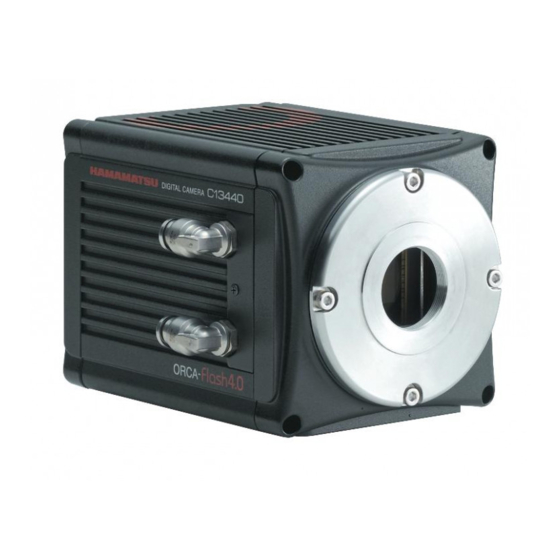
ORCA-Flash4.0 V3
Digital CMOS Camera
C13440-20CU / C13440-20CU01
Instruction manual
Thank you for your purchase
Follow the safety precautions in Chapter 1 in order to avoid personal injury and
•
damage to property when using this system. The manual describes the correct
handling method of the system and provides instructions that should be followed
to avoid accidents. Read this manual carefully before using this system. After
reading this manual, store it in a location where you can refer to it at any time.
Ver.1.3
April 2017
HAMAMATSU PHOTONICS K.K.
A3410301-03
Advertisement
Table of Contents

Related Manuals for Hamamatsu Photonics C13440-20CU


Summary of Contents for Hamamatsu Photonics C13440-20CU
-
Page 1: Instruction Manual
ORCA-Flash4.0 V3 Digital CMOS Camera C13440-20CU / C13440-20CU01 Instruction manual Thank you for your purchase Follow the safety precautions in Chapter 1 in order to avoid personal injury and • damage to property when using this system. The manual describes the correct handling method of the system and provides instructions that should be followed to avoid accidents. - Page 2 ~ Blank page ~...
-
Page 3: Safety Precautions
C13440-20CU / C13440-20CU01 Instruction manual_Ver.1.3 1. SAFETY PRECAUTIONS SYMBOLS The symbols shown below are used for this camera. Direct current Alternating current CLASSIFICATION OF WARNINGS We have classified the warnings symbols that appear in this instruction manual and on the camera as follows for your convenience. -
Page 4: Ac Adapter
C13440-20CU / C13440-20CU01 Instruction manual_Ver.1.3 Power supply Use the camera with the indicated voltage on the rating sticker. Using a different voltage can damage the camera and lead to fire or electric shock. Cables Do not to place heavy objects on cables or bend them excessively. Doing so can damage the cables and lead to fire or electric shock. -
Page 5: Mounting The Camera
C13440-20CU / C13440-20CU01 Instruction manual_Ver.1.3 AC adapter When unplugging the power supply cord, do not pull on the cord. Remove the plug from the outlet to avoid causing electric shock or fire. When unplugging the power supply cord, do not pull on the cord, but remove the plug from the camera to avoid breakdown of the AC adapter or the camera. - Page 6 C13440-20CU / C13440-20CU01 Instruction manual_Ver.1.3 Using water cooling Be careful water does not splash on the camera. Cut off the power supply of the circulating water cooler and the camera when you remove and install the cooling water hoses. Cooling water It is recommended to use soft water (except pure water) for cooling water.
-
Page 7: Check The Contents Of Package
C13440-20CU / C13440-20CU01 Instruction manual_Ver.1.3 2. CHECK THE CONTENTS OF PACKAGE When opening the package, check that the following items are included before use. If the contents are incorrect, insufficient or damaged in any way, contact a Hamamatsu subsidiary or your local distributor before attempting to operate the camera. -
Page 8: Installation
C13440-20CU / C13440-20CU01 Instruction manual_Ver.1.3 3. INSTALLATION Avoid using or storing this camera in the following places Places where the temperature is not the operating temperature indicated in the specifications • Places where the temperature is not the storage temperature indicated in the specifications •... -
Page 9: Table Of Contents
C13440-20CU / C13440-20CU01 Instruction manual_Ver.1.3 1. SAFETY PRECAUTIONS ................... 3 SYMBOLS ........................... 3 CLASSIFICATION OF WARNINGS ................... 3 2. CHECK THE CONTENTS OF PACKAGE ............7 3. INSTALLATION ....................8 4. OVERVIEW ....................... 11 5. FEATURES ....................... 12 6. NAME AND FUNCTION OF PARTS ..............15 7. - Page 10 C13440-20CU / C13440-20CU01 Instruction manual_Ver.1.3 14. SPECIFICATIONS .................... 82 14-1 CAMERA SPECIFICATIONS .................... 82 14-2 CONDENSATION......................85 14-3 SPECTRAL RESPONSE CHARACTERISTICS (TYP.) ........... 86 14-4 INTERFACE SPECIFICATIONS ..................87 14-5 OUTPUT TIMING SPECIFICATIONS ................89 15. DIMENSIONAL OUTLINES ................93 15-1 C13440-20CU ........................
-
Page 11: Overview
C13440-20CU / C13440-20CU01 Instruction manual_Ver.1.3 4. OVERVIEW C13440-20CU / C13440-20CU01 is equipped with the new scientific image sensor, an advanced CMOS device that realizes the multiple benefits of high resolution, high readout speed, and low noise all at once. The camera provides 4.0 megapixels resolution at 100 fps (frames/s) (and up to 25 655 fps by sub-array readout) while achieving 1.0 electrons (median) 1.6 electrons (r.m.s) readout noise... -
Page 12: Features
C13440-20CU / C13440-20CU01 Instruction manual_Ver.1.3 5. FEATURES (1) Readout noise In the camera, the pixel amplifier is optimized: it has high gain from optimizing the semiconductor process, and the difference among pixel amplifiers are greatly minimized. In addition, there is on-chip CDS (correlated double sampling) circuit, which plays an important role in achieving low noise. - Page 13 C13440-20CU / C13440-20CU01 Instruction manual_Ver.1.3 (8) Interface This camera has both Camera Link and USB 3.0 interface. Camera Link Interface: The camera Link interface is able to transfer large volumes of data. It can transfer a 4 megapixels image with 100 fps.
- Page 14 C13440-20CU / C13440-20CU01 Instruction manual_Ver.1.3 (10) Camera operation modes The camera has three operation modes: 1) Free running mode, in which the exposure and readout timing are controlled by the internal microprocessor, and 2) External trigger mode, in which the exposure and readout timing are decided by an external trigger. 3) Start trigger mode is used to start operating the camera by a trigger input for a continuous imaging.
-
Page 15: Name And Function Of Parts
C13440-20CU / C13440-20CU01 Instruction manual_Ver.1.3 6. NAME AND FUNCTION OF PARTS (1) C13440-20CU (C-mount type) Figure 6-1 (2) C13440-20CU01 (F-mount type) Figure 6-2... - Page 16 (Do not block ventilation openings.). a. Lens mount C13440-20CU can be attached to C-mount lens or an optics system. C13440-20CU01 can be attached to F-mount lens or an optics system. •...
- Page 17 C13440-20CU / C13440-20CU01 Instruction manual_Ver.1.3 h. Power switch [POWER] The power is turned on/off. - When the power switch is set to "ON", the camera turns on and starts initialization and the lamp blinks in green. - When the initialization is completed, the lamp color stays in green.
-
Page 18: Connection
C13440-20CU / C13440-20CU01 Instruction manual_Ver.1.3 7. CONNECTION Refer to the figure when connecting the various cables. (1) Camera Link interface Camera (Rear) Computer Circuit water cooler to connector 2 to connector 1 Camera Link interface board Figure 7-1 (2) USB 3.0 interface... - Page 19 C13440-20CU / C13440-20CU01 Instruction manual_Ver.1.3 a. AC adapter This is the cord to supply a power supply. Use the accessory AC adapter. b. Cooling water hose (at Water-cooling: Option) It connects the camera and circulating water cooler. The insert position of WATER IN/OUT on the camera WATER connector is not specified.
-
Page 20: Water Cooling
C13440-20CU / C13440-20CU01 Instruction manual_Ver.1.3 8. WATER COOLING Improper handling of the camera without observing these cautions could lead to • personal injury to the user or damage to property. CAUTIONS (1) Change the cooling method The default setting of cooling method is Air-cooling. Cooling mode can be changed by software which is called, “DCAM Configurator”. - Page 21 C13440-20CU / C13440-20CU01 Instruction manual_Ver.1.3 (5) Handling of the circulating water cooler Handle the circulating water cooler and the cooling water according to an instruction manual of the circulating water cooler. Proper performance may not be achievable if a non-recommended circulating water cooler is used.
-
Page 22: Connection Of Water Cooling Hoses
C13440-20CU / C13440-20CU01 Instruction manual_Ver.1.3 CONNECTION OF WATER COOLING HOSES WATER connector Water cooling hose Figure 8-3 1. Place the camera on the stable table. 2. Connect water cooling hose into the WATER connector on the camera. - Insert the hose fully into the WATER connector on the camera. (as shown in Figure 8-3) - Confirm the hose stops at it. -
Page 23: Disconnection Of Water Cooling Hoses
C13440-20CU / C13440-20CU01 Instruction manual_Ver.1.3 DISCONNECTION OF WATER COOLING HOSES Remove the water cooling hoses only when it is necessary to remove. • Cooling water may be left inside the camera even after hoses are removed. In such • case, remove water inside by blowing air from connectors. Be careful not to splash water onto the camera. -
Page 24: Operations
C13440-20CU / C13440-20CU01 Instruction manual_Ver.1.3 9. OPERATIONS OPERATING PRECAUTIONS Be careful of the following when you operate the camera. (1) Cooling method Cooling of this equipment is done using a Peltier element. With a Peltier element, when current is supplied, one surface is cooled, and the other surface is heated. -
Page 25: Preparating For Imaging
C13440-20CU / C13440-20CU01 Instruction manual_Ver.1.3 PREPARATING FOR IMAGING Use the following procedure when start operating the camera. • When you connect cables, turn off the power supply of the camera and the peripheral devices. • After cooling mode was changed, the camera memorizes the last setting as the default setting for Note cooling. -
Page 26: Startup Dcam Configurator
C13440-20CU / C13440-20CU01 Instruction manual_Ver.1.3 STARTUP DCAM CONFIGURATOR The following is a procedure to startup “DCAM Configurator”. 1. Open “Setup.exe” in the DCAM-API software’s folder. If the DCAM-API software is not installed on your computer, insert the media of DCAM-API software in the slot of your computer. - Page 27 C13440-20CU / C13440-20CU01 Instruction manual_Ver.1.3 4. “DCAM Configurator” window is displayed. The startup is completed with this. - Even if the camera's power supply is turned off, the state of setting is kept. - The state of setting can confirm according to “Hardware” icon on DCAM Configurator window.
-
Page 28: Description Of Cmos Image Sensor
C13440-20CU / C13440-20CU01 Instruction manual_Ver.1.3 10. DESCRIPTION OF CMOS IMAGE SENSOR 10-1 THEORY OF CMOS IMAGE SENSOR The pixel of a CMOS image sensor is composed of the photodiode and the amplifier that converts the charge into voltage. Entered light is converted to charge and converted to voltage in the pixel. -
Page 29: Readout Method Of Cmos Image Sensor
C13440-20CU / C13440-20CU01 Instruction manual_Ver.1.3 10-2 READOUT METHOD OF CMOS IMAGE SENSOR The exposure and the readout method of CMOS image sensor which this camera adopts is rolling shutter. In the rolling shutter, the exposure and readout are done line by line. Therefore, the exposure timing is different on one screen. -
Page 30: Description Of Various Functions
C13440-20CU / C13440-20CU01 Instruction manual_Ver.1.3 11. DESCRIPTION OF VARIOUS FUNCTIONS 11-1 NORMAL AREA MODE 11-1-1 CAMERA READOUT MODES (READOUT DIRECTION) The camera reads out the image sensor from the center line to the top and from the center line to the bottom simultaneously (center line is depicted in red line in the diagram). - Page 31 C13440-20CU / C13440-20CU01 Instruction manual_Ver.1.3 11-1-3 READOUT SPEED (SCAN SPEED) The standard scan readout speed can achieve a frame rate of 100 fps for full resolution with low noise (1.0 electrons (median), 1.6 electrons (r.m.s.)), and the slow scan readout speed can achieve even lower noise (0.8 electrons (median), 1.4 electrons (r.m.s.)) with a frame rate of 30 fps for full resolution.
- Page 32 C13440-20CU / C13440-20CU01 Instruction manual_Ver.1.3 11-1-4 FRAME RATE CALCULATION (1) Standard scan: Camera Link = Number of vertical line (at the center area of the image sensor) Exp1 = 1.004 ms to 10 s (input in units of seconds) = 9.744 36 µs...
- Page 33 C13440-20CU / C13440-20CU01 Instruction manual_Ver.1.3 (2) Standard scan: USB 3.0 = Number of horizontal pixel = Number of vertical line (at the center area of the image sensor) Exp1 = 1.004 ms to 10 s (input in units of seconds) = 9.744 36 µs...
- Page 34 C13440-20CU / C13440-20CU01 Instruction manual_Ver.1.3 2. 12 bit Digital output Horizontal Frame Operation modes Binning Calculation formula Hn × Vn rate (fps) Vertical Free running 2048 × 2048 Hn>512 mode 1/(round(Vn/2048/53/1H) ×1H) 2048 × 512 Vn≥16 2048 × 64 1710 Hn>512...
- Page 35 C13440-20CU / C13440-20CU01 Instruction manual_Ver.1.3 3. 8 bit Digital output Horizontal Frame rate Operation modes Binning Calculation formula Hn × Vn (fps) Vertical Free running 2048 × 2048 Hn>512 mode 1/(round(Vn/2048/80/1H) ×1H) 2048 × 512 Vn≥16 2048 × 64 2565 Hn>512...
- Page 36 C13440-20CU / C13440-20CU01 Instruction manual_Ver.1.3 (3) Slow scan: Camera Link, USB 3.0 (Common to the two interfaces) = Number of vertical line (at the center area of the image sensor) Exp1 = 3.021 ms to 10 s (input in units of seconds) = 32.4812 µs...
- Page 37 C13440-20CU / C13440-20CU01 Instruction manual_Ver.1.3 11-1-5 CONFIGURING EXPOSURE TIME The exposure time setting can be done by the units of seconds. The actual exposure time setting is defined by the following formula, and the camera automatically calculates a longer and closest value from the specified exposure time setting.
-
Page 38: Camera Operation Modes
C13440-20CU / C13440-20CU01 Instruction manual_Ver.1.3 11-1-6 CAMERA OPERATION MODES 11-1-6-1 Free running mode The camera has Free running mode which the exposure and readout timing can be set and controlled by an internal microprocessor. Free running mode has normal readout mode (in which the exposure time is longer than the 1 frame readout time) and electrical shutter mode (in which the exposure time is shorter than the 1 frame readout time). - Page 39 C13440-20CU / C13440-20CU01 Instruction manual_Ver.1.3 (2) Electrical shutter The electrical shutter mode is used to get a proper signal level when signal overflow happens due to too much input photons in normal readout mode. In this mode, the fastest frame rate is 100 fps (standard scan via Camera Link), 40 fps (standard scan via USB 3.0) or 30 fps (slow scan) at full...
- Page 40 C13440-20CU / C13440-20CU01 Instruction manual_Ver.1.3 11-1-6-2 External trigger mode The camera has various external trigger functions to synchronize the camera with the external equipment. In External trigger mode, the external equipment becomes a master and the camera becomes a slave.
- Page 41 C13440-20CU / C13440-20CU01 Instruction manual_Ver.1.3 (2) Global reset Edge trigger mode Global reset function enables to reset the electric charge of all pixels at the same time. Then all pixels can start exposure at the same time. With this Global reset Edge trigger mode, the exposure of all pixels begins on the edge (rising / falling) timing of the input trigger signal into the camera.
- Page 42 C13440-20CU / C13440-20CU01 Instruction manual_Ver.1.3 (3) Level trigger mode The Level trigger mode is used to control both exposure start timing and exposure time length by inputting external trigger pulses. In this mode, the camera starts exposure at the start of high or low period of the input trigger pulse and stops exposure at the end of high or low period of the input trigger pulse.
- Page 43 C13440-20CU / C13440-20CU01 Instruction manual_Ver.1.3 (4) Global reset Level trigger mode Global reset function enables to reset the electric charge of all pixels at the same time. Then all pixels can start exposure at the same time. The example below is for the trigger level High. With this Global reset Level trigger mode, the exposure of all pixels begins when the trigger signal becomes High.
- Page 44 C13440-20CU / C13440-20CU01 Instruction manual_Ver.1.3 (5) Synchronous readout trigger mode The Synchronous readout trigger mode is used for continuous imaging when it is necessary to control the exposure start timing of each frame from an external source. It is useful for confocal microscopy.
- Page 45 C13440-20CU / C13440-20CU01 Instruction manual_Ver.1.3 Trigger Times; Also in the Synchronous readout trigger mode, synchronous readout can be controlled by specifying, the number of timing pulses to determine the exposure time. The following figure shows the exposure timing when the Trigger Times is set as 3.
- Page 46 C13440-20CU / C13440-20CU01 Instruction manual_Ver.1.3 11-1-6-3 Start trigger mode Start trigger mode is to start operating the camera by a trigger input for a continuous imaging. It is useful to secure the frame rate as fast as possible when continuous image acquisition and not to sacrifice the exposure time.
- Page 47 C13440-20CU / C13440-20CU01 Instruction manual_Ver.1.3 11-1-7 TRIGGER OUTPUT The camera provides a range of trigger output signals to synchronize with an external instrument and the camera becomes the master and the external instrument becomes the slave. There are three different trigger output functions as follows.
- Page 48 C13440-20CU / C13440-20CU01 Instruction manual_Ver.1.3 Figure 11-12 Programmable timing output (3) Trigger ready output The trigger ready output is useful to make the frame intervals as short as possible in external trigger mode. For example, when the camera is working in the Edge trigger mode, the next frame can start after the previous frame exposure is done.
-
Page 49: Lightsheet Readout Mode
C13440-20CU / C13440-20CU01 Instruction manual_Ver.1.3 11-2 LIGHTSHEET READOUT MODE Lightsheet Readout Mode is a unique feature of CMOS image sensor which provides improved control over the rolling shutter mechanism. By finely synchronizing the camera readout with the illumination scan, scattered light is rejected allowing images of higher signal to noise ratios to be acquired. - Page 50 C13440-20CU / C13440-20CU01 Instruction manual_Ver.1.3 11-2-2 ABOUT READOUT AT LIGHTSHEET READOUT MODE (1) Readout methods This mode can set Normal readout and Sub-array readout. Binning readout mode is not supported at Lightsheet Readout Mode. The size and the position of the sub-array readout can be configured according to the table below.
- Page 51 C13440-20CU / C13440-20CU01 Instruction manual_Ver.1.3 (2) USB 3.0 = Number of horizontal pixel = Number of vertical line Exp1 = 9.744 36 µs to 10 s (input in units of seconds to the calculation formula) = 9.744 36 µs to 100 ms...
- Page 52 C13440-20CU / C13440-20CU01 Instruction manual_Ver.1.3 11-2-5 TIMING DIAGRAM (1) Free running mode Figure 11-17 (Ex. Top to bottom readout) (2) Edge trigger mode (External trigger mode) Figure 11-18 (Ex. rising edge, Top to bottom readout)
- Page 53 C13440-20CU / C13440-20CU01 Instruction manual_Ver.1.3 (3) Start trigger mode Figure 11-19 (Ex. rising edge, Top to bottom readout)
- Page 54 C13440-20CU / C13440-20CU01 Instruction manual_Ver.1.3 11-2-6 TRIGGER OUTPUT The camera provides a range of trigger output signals with Lightsheet Readout Mode. The global exposure timing output is not provided, however, because there is no timing where all lines expose at the same time with Lightsheet Readout Mode.
- Page 55 C13440-20CU / C13440-20CU01 Instruction manual_Ver.1.3 Figure 11-21 Programmable timing output referenced with Hsync (Top to bottom readout) When you choose Hsync for the reference of programmable timing output, camera can output some pulses before start the exposure. It is called as Pre-Hsync. You can set the number of...
-
Page 56: W-View Mode
C13440-20CU / C13440-20CU01 Instruction manual_Ver.1.3 11-3 W-VIEW MODE The exposure time and the position of sub-array readout can be set for the top half area and the bottom half area independently in W-VIEW Mode. This function is optimized for simultaneous image acquisition of dual wavelength images. - Page 57 C13440-20CU / C13440-20CU01 Instruction manual_Ver.1.3 11-3-2 ABOUT READOUT AT LIGHTSHEET READOUT MODE (1) Readout methods This mode can set Normal readout, Binning readout, and Sub-array readout. In sub-array mode, the position of sub-array readout can be set independently in the top and bottom half areas.
- Page 58 C13440-20CU / C13440-20CU01 Instruction manual_Ver.1.3 11-3-3 FRAME RATE CALCULATION (1) Standard scan: Camera Link = Number of vertical line Exp1 = 1.004 ms to 2 s (input in units of seconds to the calculation formula) = 9.744 36 µs Operation modes...
- Page 59 C13440-20CU / C13440-20CU01 Instruction manual_Ver.1.3 (2) Standard scan: USB 3.0 = Number of horizontal pixel = Number of vertical line Exp1 = 1.004 ms to 2 s (input in units of seconds to the calculation formula) = 9.744 36 µs...
- Page 60 C13440-20CU / C13440-20CU01 Instruction manual_Ver.1.3 2. 12 bit Digital output Operation Horizontal Frame rate Binning Calculation formula Hn × Vn modes Vertical (fps) Free running 2048 × 1024 Hn>512 mode 1/(round(Vn/1024/53/1H) ×1H) 2048 × 256 Vn≥8 2048 × 32 1710 Hn>512...
- Page 61 C13440-20CU / C13440-20CU01 Instruction manual_Ver.1.3 3. 8 bit Digital output Operation Horizontal Frame rate Binning Calculation formula Hn × Vn modes Vertical (fps) Free running 2048 × 1024 Hn>512 mode 1/(round(Vn/1024/80/1H) ×1H) 2048 × 256 Vn≥8 2048 × 32 2565 Hn>512...
- Page 62 C13440-20CU / C13440-20CU01 Instruction manual_Ver.1.3 (3) Slow scan: Camera Link, USB 3.0 (Common to two interfaces) = Number of vertical line Exp1 = 3.021 ms to 6 s (input in units of seconds to the calculation formula) = 32.4812 µs...
- Page 63 C13440-20CU / C13440-20CU01 Instruction manual_Ver.1.3 11-3-4 CONFIGURING EXPOSURE TIME The exposure time can be set independently for the top and bottom half areas. The exposure time setting can be done by the units of seconds. The actual exposure time setting is defined by the following formula, and the camera automatically calculates a longer and closest value from the specified exposure time setting.
- Page 64 C13440-20CU / C13440-20CU01 Instruction manual_Ver.1.3 11-3-5 TIMING DIAGRAM The timing diagram in W-VIEW Mode is shown below. When different exposure time is set for the top and bottom half areas, the end of exposure timing becomes the same. (1) Free running mode Electrical shutter mode works for the half area whose exposure time is shorter than the other half area exposure in W-VIEW Mode.
- Page 65 C13440-20CU / C13440-20CU01 Instruction manual_Ver.1.3 (2) External trigger mode, Start trigger mode The exposure time can be set independently for the top and bottom half areas with Edge trigger mode, Global reset Edge trigger mode and start trigger mode in W-VIEW Mode. The exposure time for both half areas is the same with Level trigger mode, Global reset Level trigger mode and Synchronous readout trigger mode.
- Page 66 C13440-20CU / C13440-20CU01 Instruction manual_Ver.1.3 Figure 11-28 Global reset Edge trigger mode (Ex. Top: top to center / Bottom: center to bottom) Figure 11-29 Start trigger mode (Ex. Top: top to center / Bottom: center to bottom) Note • Please contact a Hamamatsu subsidiary or your local distributor for the detail of the timing information.
- Page 67 C13440-20CU / C13440-20CU01 Instruction manual_Ver.1.3 11-3-6 TRIGGER OUTPUT The camera provides a range of trigger output signals with W-VIEW Mode. It is possible to output a pulse that shows the period where all lines in the top or bottom half area expose at the same time.
-
Page 68: Dual Lightsheet Readout Mode
C13440-20CU / C13440-20CU01 Instruction manual_Ver.1.3 11-4 DUAL LIGHTSHEET READOUT MODE Dual Lightsheet Readout Mode is a unique feature of CMOS image sensor which provides improved control over the rolling shutter mechanism. By finely synchronizing the camera readout with the illumination scan, scattered light is rejected allowing images of higher signal to noise ratios to be acquired. - Page 69 C13440-20CU / C13440-20CU01 Instruction manual_Ver.1.3 11-4-2 ABOUT READOUT AT DUAL LIGHTSHEET READOUT MODE (1) Readout methods This mode can set Normal readout and Sub-array readout. Binning readout mode is not supported at Dual Lightsheet Readout Mode. The size and the position of the sub-array readout can be configured according to the table below.
- Page 70 C13440-20CU / C13440-20CU01 Instruction manual_Ver.1.3 (2) USB 3.0 = Number of horizontal pixel = Number of vertical line Exp1 = 9.744 36 µs to 10 s (input in units of seconds to the calculation formula) = 9.744 36 µs to 100 ms...
- Page 71 C13440-20CU / C13440-20CU01 Instruction manual_Ver.1.3 11-4-4 READOUT TIME OF THE HORIZONTAL LINE Readout time and exposure time can be varied with Dual Lightsheet Readout Mode for synchronizing the camera readout with the illumination scan. = Number of vertical line = 9.744 36 µs to 100 ms Readout time = Vn ×...
- Page 72 C13440-20CU / C13440-20CU01 Instruction manual_Ver.1.3 (2) Edge trigger mode Figure 11-36 (Ex. rising edge, Top: top to center / Bottom: center to bottom) (3) Start trigger mode Figure 11-37 (Ex. rising edge, Top: top to center / Bottom: center to bottom)
- Page 73 C13440-20CU / C13440-20CU01 Instruction manual_Ver.1.3 11-4-6 TRIGGER OUTPUT The camera provides a range of trigger output signals with Dual Lightsheet Readout Mode. The global exposure timing output is not provided, because there is no timing where all lines expose at the same time with Dual Lightsheet Readout Mode.
-
Page 74: Real-Time Defect Pixel Correction
C13440-20CU / C13440-20CU01 Instruction manual_Ver.1.3 External trigger Exposure ・ ・ 1023H 1024H Exposure 2046H 2047H Hsync Delay Pulse Width Figure 11-39 Programmable timing output referenced with Hsync (Top: top to center / Bottom: center to bottom) When you choose Hsync for the reference of programmable timing output, camera can output some pulses before start the exposure. -
Page 75: Data Reduction Functions
C13440-20CU / C13440-20CU01 Instruction manual_Ver.1.3 11-6 DATA REDUCTION FUNCTIONS The camera provides 4.0 megapixels resolution at 100 fps and 16 bit of gradation. Then the camera outputs 800 MB of data per second, and large capacity of storage device would be necessary to store such a large amount of data. - Page 76 C13440-20CU / C13440-20CU01 Instruction manual_Ver.1.3 11-6-2 12 BIT / 8 BIT DIGITAL OUTPUT The amount of data can be reduced by 12 bit or 8 bit digital output. The amount of data can be three quarters of original 16 bit data and each pixel have 4096 steps of gradation with 12 bit digital output.
-
Page 77: Master Pulse
C13440-20CU / C13440-20CU01 Instruction manual_Ver.1.3 11-7 MASTER PULSE The camera has master pulse function which can generate pulses that is independent of the exposure or readout timing of image sensor. External trigger mode can work synchronized with the timing pulses that the master pulse generates, except for External trigger mode in Lightsheet Readout Mode and Dual Lightsheet Readout Mode. - Page 78 C13440-20CU / C13440-20CU01 Instruction manual_Ver.1.3 (3) Burst mode The camera starts generating pulses inside of the camera by input trigger signal, and the camera stops generating pulses after the specified number of pulses are generated. And then, the camera will be ready for the next input trigger signal.
-
Page 79: Maintenance
C13440-20CU / C13440-20CU01 Instruction manual_Ver.1.3 12. MAINTENANCE 12-1 CARE Perform cleaning of this equipment with the dry soft cloth. • Do not wipe with a damp cloth or unclean cloth. Then, the glass window on the image sensor should be cleaned according to the following. -
Page 80: Information On Cooling Water For The Circulating Water Cooler
C13440-20CU / C13440-20CU01 Instruction manual_Ver.1.3 12-2 INFORMATION ON COOLING WATER FOR THE CIRCULATING WATER COOLER • Regarding handling cooling water and circulating water cooler, please refer to instruction manual attached to the circulating water cooler. • It is recommended to use soft water (except pure water) for cooling water. -
Page 81: Troubleshooting
C13440-20CU / C13440-20CU01 Instruction manual_Ver.1.3 13. TROUBLESHOOTING If an abnormality occurs, look up the possible causes in the following tables and, if necessary, report the details to Hamamatsu subsidiary or your local distributor. 13-1 IMAGE IS NOT TRANSFERRED Cause Measures... -
Page 82: Specifications
C13440-20CU / C13440-20CU01 Instruction manual_Ver.1.3 14. SPECIFICATIONS 14-1 CAMERA SPECIFICATIONS (1) Electric specifications Camera Link interface USB 3.0 interface Imaging device Scientific CMOS image sensor Effective number of pixels 2048 (H) × 2048 (V) 6.5 μm (H) × 6.5 µm (V) - Page 83 C13440-20CU / C13440-20CU01 Instruction manual_Ver.1.3 Camera Link interface USB 3.0 interface Readout mode Binning readout mode 2×2,4×4 (Digital binning) * Sub-array readout mode Sub-array readout mode (Configurable for each vertical 4 (Configurable for each vertical 4 pixels and horizontal 128 pixels.) pixels and horizontal 128 pixels.)
- Page 84 C13440-20CU / C13440-20CU01 Instruction manual_Ver.1.3 Camera Link interface USB 3.0 interface External input External input External signal input (SMA connector, Camera Link) (SMA connector) External trigger input level 3.3 V LVCMOS level External trigger delay function 0 µs to 10 s (1 µs step)
-
Page 85: Condensation
C13440-20CU / C13440-20CU01 Instruction manual_Ver.1.3 (4) Dimensional outline and weight Dimensional outline 85 mm × 93.5 mm × 125 mm Weight Approx. 2.2 kg (Camera only) • Be careful not to drop off the camera or not drop underfoot when making it move because it is approx. -
Page 86: Spectral Response Characteristics (Typ.)
C13440-20CU / C13440-20CU01 Instruction manual_Ver.1.3 14-3 SPECTRAL RESPONSE CHARACTERISTICS (TYP.) Figure 14-2... -
Page 87: Interface Specifications
C13440-20CU / C13440-20CU01 Instruction manual_Ver.1.3 14-4 INTERFACE SPECIFICATIONS (1) Camera Link interface The camera transfers 80 bit data in parallel (8 bit x 10 port). It is an extended interface of Camera Link full configuration Standard. 1. Pin assignments of Camera Link connector 1 (SDR-26) - Page 88 C13440-20CU / C13440-20CU01 Instruction manual_Ver.1.3 3. Camera Link bit assignments 28 bit solution Plug No.1, Plug No.2, Plug No.3, Port Port Port pin name Channel Link X Channel Link Y Channel Link Z TxIN0 Port A0 D0_0 Port D2 D1_10...
-
Page 89: Output Timing Specifications
C13440-20CU / C13440-20CU01 Instruction manual_Ver.1.3 14-5 OUTPUT TIMING SPECIFICATIONS The following shows output timing specifications for 16 bit digital output. (1) Normal readout Camera Link Timing (Normal) C.L Fvalid C.L Lvalid C.L Fvalid V1023 V1024 V1022 V2045 V2046 V2047 C.L Lvalid... - Page 90 C13440-20CU / C13440-20CU01 Instruction manual_Ver.1.3 (2) 2x2 binning readout Camera Link Timing (2x2 Binning) C.L Fvalid C.L Lvalid C.L Fvalid V511 V512 V510 V1021 V1022 V1023 C.L Lvalid Tx Clock 85 MHz CL Fvalid 205 clock 209 clock V511 V512...
- Page 91 C13440-20CU / C13440-20CU01 Instruction manual_Ver.1.3 (3) 4x4 binning readout Camera Link Timing (4x4 Binning) C.L Fvalid C.L Lvalid C.L Fvalid V255 V256 V254 V509 V510 V511 C.L Lvalid Tx Clock 85 MHz CL Fvalid 103 clock 311 clock V256 V255...
- Page 92 C13440-20CU / C13440-20CU01 Instruction manual_Ver.1.3 (4) Sub-array readout Camera Link Timing (Vertical Sub Array 2 same size regions readout) C.L Fvalid C.L Lvalid C.L Fvalid V(o1+w) V(o2) V(o1+w-1) V(o1-2) V(o2+w-2) V(o1-1) V(o2 +w-1) V(o1) V(o2+w) C.L Lvalid Tx Clock 85 MHz...
-
Page 93: Dimensional Outlines
C13440-20CU / C13440-20CU01 Instruction manual_Ver.1.3 15. DIMENSIONAL OUTLINES 15-1 C13440-20CU... -
Page 94: C13440-20Cu01
C13440-20CU / C13440-20CU01 Instruction manual_Ver.1.3 15-2 C13440-20CU01... -
Page 95: Warranty
2. If you have any trouble or are unclear about anything, contact a Hamamatsu subsidiary or your local distributor giving the product name, serial number and details of the problem. If Hamamatsu Photonics consider the problem to be a malfunction, we will decide whether dispatch an engineer or have the camera returned to us for repairs. -
Page 96: Contact Information
C13440-20CU / C13440-20CU01 Instruction manual_Ver.1.3 17. CONTACT INFORMATION Manufacturer HAMAMATSU PHOTONICS K. K., Systems Division 812 Joko-cho, Higashi-ku, Hamamatsu City, Shizuoka Pref., 431-3196, Japan Telephone (81) 53-431-0124, Fax: (81) 53-435-1574 E-mail: export@sys.hpk.co.jp Local contact information worldwide can be found at: www.hamamatsu.com...
Need help?
Do you have a question about the C13440-20CU and is the answer not in the manual?
Questions and answers