Table of Contents
Advertisement
Quick Links
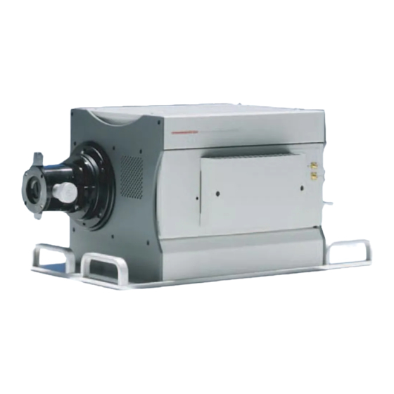
Universal streak camera
C10910
Instruction Manual
Thank you for your purchase.
•
Follow the safety precautions in Chapter 1 in order to avoid personal injury
and damage to property when using this system. The manual describes the
CAUTION
correct handling method of the system and provides instructions that should
be followed to avoid accidents. Read this manual carefully before using
this system. After reading this manual, store it in a location where you can
refer to it at any time.
Ver.1.19E
MAY 2018
HAMAMATSU PHOTONICS K.K.
87550301-19
Advertisement
Table of Contents

Related Manuals for Hamamatsu Photonics C10910


Summary of Contents for Hamamatsu Photonics C10910
- Page 1 Read this manual carefully before using this system. After reading this manual, store it in a location where you can refer to it at any time. Ver.1.19E MAY 2018 HAMAMATSU PHOTONICS K.K. 87550301-19...
-
Page 3: Safety Precautions
C10910 INSTRUCTION MANUAL Ver.1.19E 1. SAFETY PRECAUTIONS SYMBOLS The symbols shown below are used for this system. Protective conductor terminal Alternating current ON (supply) OFF (supply) CLASSIFICATION OF WARNINGS We have classified the warnings symbols that appear in this instruction manual and on the system as follows for your convenience. - Page 4 C10910 INSTRUCTION MANUAL Ver.1.19E WARNING Power supply Use the system with the indicated voltage on the rating sticker. Using a different voltage can damage the system and lead to fire or electric shock. Cables Do not to place heavy objects on cables or bend them excessively. Doing so can damage the cables and lead to fire or electric shock.
- Page 5 C10910 INSTRUCTION MANUAL Ver.1.19E CAUTION Power supply cord When unplugging the power supply cord, do not pull on the cord. Remove the plug from the outlet to avoid causing electric shock or fire. If the system is not in use for a long period of time, unplug the power supply cord from the outlet to avoid damaging the cord and causing electric shock or fire.
- Page 6 C10910 INSTRUCTION MANUAL Ver.1.19E CAUTION Streak tube The system has a built-in highly-sensitivity streak tube with a very high photon detection capability. Because of this, excessive incident light can damage the streak tube. The streak camera operation should be handled with extreme care to avoid damage.
-
Page 7: Check The Contents Of Package
When opening the package, check that the following items are included before use. If the contents are incorrect, insufficient, or damaged in any way, contact a Hamamatsu subsidiary or your local distributor before attempting to operate the system. C10910-XX Universal streak camera main unit C10910 Universal streak camera main unit Power unit... - Page 8 C10910 INSTRUCTION MANUAL Ver.1.19E Option Vertical plug-in unit M10911-01 Synchroscan unit M10911-01 Synchroscan unit SMA-SMA cable SMA-BNC converter SMA-50 Ω termination SWR cable(LEMO – red and black banana plug) M10911-02 250 MHz synchroscan unit M10911-02 250 MHz synchroscan unit SMA-SMA cable SMA-BNC converter SMA-50 Ω...
- Page 9 C10910 INSTRUCTION MANUAL Ver.1.19E Horizontal plug-in unit M10914-01 Horizontal blanking unit M10914-01 Horizontal blanking unit is attached to C10910-XX Universal streak camera main unit. M10914-02 Shift blanking unit M10914-02 Shift blanking unit BNC-BNC cable 1.5 m M10915-01 Synchronous blanking unit...
- Page 10 C10910 INSTRUCTION MANUAL Ver.1.19E Input optics A1976-01 input optics for streak camera A1976-01 input optics for streak camera A1974 input optics for streak camera A1974 input optics for streak camera Output optics A11695-01 50:35 output optics for streak camera A11695-01 50:35 output optics for streak camera...
-
Page 11: Table Of Contents
C10910 INSTRUCTION MANUAL Ver.1.19E 1. SAFETY PRECAUTIONS ................1 SYMBOLS ........................1 CLASSIFICATION OF WARNINGS ................1 2. CHECK THE CONTENTS OF PACKAGE ........... 5 3. OVERVIEW ....................12 OVERVIEW ......................... 12 OPERATING PRINCIPLE ................... 12 CHARACTERISTICS ....................13 3-3-1 TEMPORAL RESOLUTION ................... - Page 12 C10910 INSTRUCTION MANUAL Ver.1.19E 6-7-6 FOCUSING OF OPTICS ....................46 7. CONNECTION WITH THE COMPUTER FOR CONTROL......48 OVERVIEW ......................... 48 CONNECTION ......................48 DRIVER INSTALL ....................... 48 HOW TO SET THE USB ADDRESS ................50 8. OPERATIONS ................... 51 CAUTION ........................
- Page 13 14-3-2 SHUTTER REPLACEMENT................... 77 15. SPECIFICATIONS ..................78 15-1 N12142 STREAK TUBE....................78 15-2 C10910 MAIN UNIT AND STREAK TUBE ..............78 15-3 M10911 SYNCHROSCAN UNIT SEREIS ..............80 15-4 M10912 FAST SINGLE SWEEP UNIT SERIES ............81 15-5 M10913 SLOW SINGLE SWEEP UNIT SERIES ............82 15-6 M10914 HORIZONTAL BLANKING UNIT SERIES ............
-
Page 14: Overview
3. OVERVIEW OVERVIEW The C10910 Streak Camera can be used as a synchroscan sweep model (with a temporal resolution of 1 ps or better *1), as a fast single sweep model (with a temporal resolution of 1 ps or better *1), or as a slow single sweep model (with a temporal resolution of 20 ps or better), simply by replacing the plug-in module. -
Page 15: Characteristics
C10910 INSTRUCTION MANUAL Ver.1.19E E: Phosphor screen Luminescence light is happened when electrons are came. The light passes through a slit and forms an image on the photocathode of the streak tube. The photocathode converts the light into electrons, and these electrons are directed towards a phosphor screen by accelerating mesh. -
Page 16: Dynamic Range
(1 ps about C10910) due to the intensity-dependency, and the point corresponding to the noise level of the readout system. - Page 17 C10910 INSTRUCTION MANUAL Ver.1.19E Gating: This is an operation carried out in order to render the streak camera temporarily insensitive. If light positioned before and after the measured light is entered to the streak camera, the photoelectrons produced by that light will be scattered and multiplied inside the streak tube, which causes optical noise to appear on the streak image, and lower the S/N of the streak image.
- Page 18 C10910 INSTRUCTION MANUAL Ver.1.19E multiplied into as many as 1000 using this process. Output Optics: This is an optics which is positioned between the phosphor screen and the readout camera. It is used to form an image on the readout camera which reads the streak image formed on the phosphor screen.
- Page 19 C10910 INSTRUCTION MANUAL Ver.1.19E Temporal Resolution: This is the boundary of the resolution capability which differentiates two phenomena which are consecutive in terms of time. It is defined by the FWHM of the intensity of the streak image for the incident light with a time width (pulse width) which can be infinitely close to but not equal to zero.
-
Page 20: Protective Functions Of The Streak Camera
Since no sweep deflection is performed in FOCUS mode, incoming light intensity is concentrated within the slit image and can cause burn-in or gain degradation at the MCP intensifier. The C10910 is designed to close the shutter automatically when continuous operation time in FOCUS mode reaches (approx. -
Page 21: Name And Functions Of Parts
C10910 INSTRUCTION MANUAL Ver.1.19E 5. NAME AND FUNCTIONS OF PARTS UNIVERSAL STREAK CAMERA MAIN UNIT (SIDE VIEW FROM VERTICAL PLUG-IN UNIT SIDE) ① ② ③ Fig. 5-1 ① Insert position of vertical plug-in Insert vertical plug-in. • Do not touch the EMC shield parts at this position. If touch,... -
Page 22: Universal Streak Camera Main Unit (Top View From Horizontal Plug-In Unit Side)
C10910 INSTRUCTION MANUAL Ver.1.19E UNIVERSAL STREAK CAMERA MAIN UNIT (TOP VIEW FROM HORIZONTAL PLUG-IN UNIT SIDE) ① ② ④ ④ ③ Fig. 5-2 ① Insert position of horizontal plug-in Insert horizontal plug-in. • Do not touch the EMC shield parts at this position. If touch,... -
Page 23: Universal Streak Camera Main Unit
C10910 INSTRUCTION MANUAL Ver.1.19E UNIVERSAL STREAK CAMERA MAIN UNIT (TOP VIEW FROM HORIZONTAL PLUG-IN UNIT SIDE) ① ① Fig. 5-3 ① Air inlet or outlet This is the inlet or the outlet for the heat ventilation. • Make sure a space of at least 10 cm is available at the back of the unit for ventilation. -
Page 24: Universal Streak Camera Main Unit(Side View From Input Optics Side)
C10910 INSTRUCTION MANUAL Ver.1.19E UNIVERSAL STREAK CAMERA MAIN UNIT(SIDE VIEW FROM INPUT OPTICS SIDE) ① ② ① ① ① ① Fig. 5-4 ① Base unit for input optics Loosen five screws when move input optics horizontally. Shutter unit is fixed inside the base unit. -
Page 25: Universal Streak Camera Main Unit (Side View From Output Optics Side)
Detach the lens cap when attach the CCD camera. ③ Power connector [POWER IN] Connect the power supply unit for C10910 and main unit with dedicated power cable. ④ Gate trigger [GATE IN] Input trigger to this terminal when use gate function. -
Page 26: Power Supply Unit (Front Panel)
C10910 INSTRUCTION MANUAL Ver.1.19E ⑧ Air outlet This is the outlet for the heat ventilation. • Make sure a space of at least 10 cm is available at the back of the unit for ventilation. • In order to prevent an internal rise in heat, do not cover these holes. -
Page 27: Power Supply Unit (Rear Panel)
③ Fig. 5-7 ① Power connector [POWER OUT] Connect the C10910 main unit and power supply unit with dedicated power cable. • Be sure to power off before inserting or removing this cable to WARNING avoid electric shock of hazardous voltage. This unit use high voltage. -
Page 28: M10911-01 Synchroscan Unit M10911-02 250 Mhz Synchroscan Unit N10911-03 Synchroscan Unit
C10910 INSTRUCTION MANUAL Ver.1.19E M10911-01 SYNCHROSCAN UNIT M10911-02 250 MHZ SYNCHROSCAN UNIT N10911-03 SYNCHROSCAN UNIT ① ② ④ ⑤ ③ Fig. 5-8 ① RF signal input terminal [SYNC.IN] Synchroscan trigger RF signal input SMA connector. The trigger power should range between -3 dBm and +17 dBm at 50 Ω. -
Page 29: M10912-01 Fast Single Sweep Unit
C10910 INSTRUCTION MANUAL Ver.1.19E M10912-01 FAST SINGLE SWEEP UNIT Front panel ① ③ ④ ② ⑤ Fig. 5-9 ① Trigger input LED [TRIG’D] When operate mode is selected, if sweep trigger is received, the light will be switched ② Trigger signal input terminal [TRIG.IN] ±... - Page 30 C10910 INSTRUCTION MANUAL Ver.1.19E Note 1: Supplementary description Currently, checking the frequency at which the streak camera is actually operating requires hooking an oscilloscope or a frequency counter to the Monitor out terminal. The output from this terminal is synchronized with the sweep. Inputting a high repetition signal of more than 10 kHz may sometimes make it difficult to get stable repetition in the output signal due to repetition limits.
-
Page 31: M10913-01, -11 Slow Single Sweep Unit
C10910 INSTRUCTION MANUAL Ver.1.19E 5-10 M10913-01, -11 SLOW SINGLE SWEEP UNIT ① ③ ② ④ ⑦ ⑤ ⑥ Fig. 5-10 ① Trigger input LED [TRIG’D] When operate mode is selected, if sweep trigger is received, the light will be switched on. - Page 32 C10910 INSTRUCTION MANUAL Ver.1.19E ⑦ Air inlet This is the inlet for the heat ventilation. • Make sure a space of at least 10 cm is available at the back of the unit for ventilation. • In order to prevent an internal rise in heat, do not cover these holes.
-
Page 33: M10914-01 Horizontal Blanking Unit
C10910 INSTRUCTION MANUAL Ver.1.19E 5-11 M10914-01 HORIZONTAL BLANKING UNIT ① Fig. 5-11 ① Cooling hole These are holes for cooling. • In order to prevent an internal rise in heat, do not cover these holes. Avoid dropping some stuff. -
Page 34: M10914-02 Shift Blanking Unit
C10910 INSTRUCTION MANUAL Ver.1.19E 5-12 M10914-02 SHIFT BLANKING UNIT ① operate ③ ② Fig. 5-12 This unit can be used with only M10911-01 or M10911-03 synchroscan unit. ① Cooling hole These are holes for cooling. • In order to prevent an internal rise in heat, do not cover these holes. Avoid dropping some stuff. - Page 35 C10910 INSTRUCTION MANUAL Ver.1.19E ③ Trigger signal input terminal [TRIG.IN] ± 5 V, 50 Ω). Maximum repetitions is SMA connector for the sweep timing trigger input ( 10 kHz. The trigger voltage should range between -5 V and +5 V at 50 Ω. Plug-in •...
-
Page 36: M10915-01 Synchronous Blanking Unit
C10910 INSTRUCTION MANUAL Ver.1.19E 5-13 M10915-01 SYNCHRONOUS BLANKING UNIT ② ① Fig. 5-13 This unit can be used with only M10911-01 synchroscan unit. ① Heatsink • Do not place a thing around this for cooling. ② Maintenance cover • Do not remove a cover, when there are no directions in particular from... -
Page 37: M10916-01 Dual Time Extender Unit M10916-02,-03 High Repetition Dual Time Extender Unit
C10910 INSTRUCTION MANUAL Ver.1.19E 5-14 M10916-01 DUAL TIME EXTENDER UNIT M10916-02,-03 HIGH REPETITION DUAL TIME EXTENDER UNIT ① ③ ④ ⑤ ⑥ ② Fig. 5-14 ① Cooling hole These are holes for cooling. • In order to prevent an internal rise in heat, do not cover these holes. Avoid dropping some stuff. - Page 38 C10910 INSTRUCTION MANUAL Ver.1.19E ④ Stability control [STABILITY] If the repetition frequency of the sweep trigger signal fully matches the maximum repetition frequency of the fast single sweep unit, then the actual sweep repetition frequency may become unstable. If that happens, then the STABILITY control can be used to perform sweeps at a stable repetition frequency.
-
Page 39: System Setup
C10910 INSTRUCTION MANUAL Ver.1.19E 6. SYSTEM SETUP THE CAUTIONS ABOUT INSTALLATION Avoid using or storing this system in the following places. Places where the temperature is not the operating temperature indicated in the specifications. Places where the temperature is not the storage temperature indicated in the specifications. -
Page 40: Installation On An Optical Table
INSTALLATION ON AN OPTICAL TABLE Secure the streak camera main unit to an optical table whenever possible. Four M4 screw holes are provided to secure the C10910 main unit to a metric optical table (M6-1.0 holes on 25 mm grid). -
Page 41: Connecting Power Cable
C10910 INSTRUCTION MANUAL Ver.1.19E CONNECTING POWER CABLE Please connect a main unit with a power supply unit by the power cable for C10910 streak camera. There is direction in connection of a power cable. Please connect after checking direction of the cable. -
Page 42: Attach Or Detach Of Vertical Plugin
C10910 INSTRUCTION MANUAL Ver.1.19E ATTACH OR DETACH OF VERTICAL PLUGIN Vertical plug-in is attached in the following procedures. (1) Be sure to check that the power supply is off. (2) Check that the position of the plug-in unit fixing handle is the end of LOOSE side. -
Page 43: Attach Or Detach Of Horizontal Plugin
C10910 INSTRUCTION MANUAL Ver.1.19E ATTACH OR DETACH OF HORIZONTAL PLUGIN Horizontal plug-in is attached in the following procedures. (1) Be sure to check that the power switch is off. (2) Insert horizontal plug-in unit in insert position of the horizontal plug-in unit.(chapter 5-2) -
Page 44: Optical Adjustment
C10910 INSTRUCTION MANUAL Ver.1.19E OPTICAL ADJUSTMENT • When you do this procedure, be sure to set up all systems included a Note read-out system. 6-7-1 INPUT OPTICS A1976-01 Confirm the appearance of the input optics and locate the below parts. -
Page 45: Input Slit Length Adjustment
The slit length is continuously adjustable in the range 0 mm to 15 mm by sliding the V-curtain vertically. Please note the effective photocathode area of the C10910 is limited to approximately 4.4 mm, therefore 4.4 mm to 15 mm setting is ineffective. In addition, the slit length should be set no longer than necessary to prevent stray light and other extraneous light from entering the streak tube. - Page 46 C10910 INSTRUCTION MANUAL Ver.1.19E (2) Four screws shown in the following photographs by the red arrow are removed, and an outside cover is removed. Please take care about fall of an outside cover. (3) Three screws shown in the following photographs by the red arrow are removed, and an inner cover is removed.
-
Page 47: Adjustment Of Slit Position
C10910 INSTRUCTION MANUAL Ver.1.19E (5) The fine adjustment plate is attached to the place in which the original adjustment plate was set, and the plate is temporarily fixed by a tape. (6) An inner cover is returned with reference to procedure (3). Next, an outside cover also returns with reference to procedure (2). -
Page 48: Focusing Of Optics
C10910 INSTRUCTION MANUAL Ver.1.19E 6-7-6 FOCUSING OF OPTICS Before you begin close the slit completely and decrease input light intensity. You can start at first by using dimmed room lights. Caution is advised while in Focus mode – since the signal density is concentrated within the slit image. - Page 49 C10910 INSTRUCTION MANUAL Ver.1.19E 6-7-6-2 Output optics The focus ring of output optics is rotated to sharpen the slit image while monitored by the readout system. If signal is weak slightly increase MCP GAIN and pay close attention to the image from readout system.
-
Page 50: Connection With The Computer For Control
CONNECTION The power supply unit is turned OFF, connect a USB cable with the computer for control. The cable attached to C10910 should be used for the USB cable. Operation may become unstable when other cables are used. DRIVER INSTALL Installation of a driver is needed when it is connected with the computer for the first time. - Page 51 Click install this drivers software anyway, although the next screen opens. Some files are installed to computer. When the following screens are appeared, installation is finished. Click the “Finish” button and close a screen. Switch on the power supply unit of C10910. A streak camera is recognized from the computer.
-
Page 52: How To Set The Usb Address
C10910 INSTRUCTION MANUAL Ver.1.19E HOW TO SET THE USB ADDRESS When you remove the maintenance switch cover on the main unit output optics side, you will see a rotary switch for USB address setting. If necessary, use this rotary switch to change the USB address. -
Page 53: Operations
C10910 INSTRUCTION MANUAL Ver.1.19E 8. OPERATIONS CAUTION In operating this system, please be careful about the following. (1) Warm-up Before operation is stable after a power supply unit is switched on and trigger inputs, it takes about 30 minutes. (2) Cables Check the connection of each cable, signal cables and power cables. -
Page 54: End Of Operations
C10910 INSTRUCTION MANUAL Ver.1.19E END OF OPERATIONS The procedure of an end should turn OFF the power supply of this system and peripheral equipment, after ending control software first. • For the prevention from an electric shock, and protection of this... -
Page 55: System Configuration Example
C10910 INSTRUCTION MANUAL Ver.1.19E 9. SYSTEM CONFIGURATION EXAMPLE C10910 Universal streak camera can respond to various measurements by exchanging a plug-in unit. The examples of fundamental plug-in connection are shown below. SYNCHROSCAN MEASUREMENT 9-1-1 CONNECTION Connect each cable based on the following figure. -
Page 56: Adjusting The Synchroscan Frequency
C10910 INSTRUCTION MANUAL Ver.1.19E 9-1-2 ADJUSTING THE SYNCHROSCAN FREQUENCY The operating frequency of the synchroscan unit is adjusted to match its usage environment. If errors occur during use or operation becomes unstable, fine-adjusting the frequency may make the operation stable. About tuning the M10911-02, contact Hamamatsu subsidiary or local distributor. If the operation is unstable, make the following adjustments: (1) Turn off the power supply unit. -
Page 57: Synchroscan Temporal Resolution
The following sections describe precautions and settings on each unit when using the C10910 and C1808-03 PIN diode head equipped with the M10911-01 or M10911-03 synchroscan unit to make measurements in combination with a laser. - Page 58 C10910 INSTRUCTION MANUAL Ver.1.19E 9-1-3-2 Installation of C1808-03(PIN DIODE HEAD) (1) Example of C1808-03 installation The example of installation of C1808-03 is shown below. Laser light is branched by a beam splitter etc. and one side is inputted into measurement for one side to C1808-03.
- Page 59 C10910 INSTRUCTION MANUAL Ver.1.19E If you can view the trigger signal on the oscilloscope, then setup is complete. The final adjustment to the input light intensity is made by adjusting the ND filter while viewing the streak image. A variable ND filter will prove convenient for adjusting the light intensity as fine as possible at this time.
-
Page 60: Sigle Sweep Measurement
CCD camera cable MONITOR OUT Computer CCD camera control BNC cable Power cable Power supply unit for C10910 Fig. 9-3 • When you connect a cable, be sure to carry out in the state of the power supply OFF. ①... -
Page 61: Plug-In Settings
C10910 INSTRUCTION MANUAL Ver.1.19E 10. PLUG-IN SETTINGS The C10910 universal streak camera includes plug-in options. Combining these plug-in modules allows a variety of setting options. These setting options are described below. See the list in the next section to find the setting items. Details of those items are also described later. -
Page 62: Horizontal Plug-In
C10910 INSTRUCTION MANUAL Ver.1.19E 10-1-3 HORIZONTAL PLUG-IN Some settings for horizontal plug-in are shown below. Model number Settings M10914-01 M10914-02 M10915-01 Sweep range OFF, 1, 2 (blanking) Delay 0 to 65 535 Trigger mode Trigger status Trigger level -4.0 V to +4.0 V... -
Page 63: Sweep Range
C10910 INSTRUCTION MANUAL Ver.1.19E 10-3 SWEEP RANGE The sweep unit has a function to select the sweep range. Changing the sweep range allows changing the full scale (time width from top end of screen to bottom end) of the streak image. To find the settable sweep range, see section 15. Specifications. -
Page 64: Mode Selector
C10910 INSTRUCTION MANUAL Ver.1.19E 10-4 MODE SELECTOR The mode selector allows choosing FOCUS mode or OPERATE mode. (1) FOCUS mode This mode is used during adjustment of the optics to check whether there is light incident on the streak camera. The input light state is easy to check because no sweep is performed. -
Page 65: Gate Mode Description
C10910 INSTRUCTION MANUAL Ver.1.19E 10-5-2 GATE MODE DESCRIPTION (1) NORMAL When a single sweep unit (M10912 fast single sweep unit series or M10913 slow single sweep unit series) is used, this mode is capable of cutting false signals that occur due to incident light generated during the return sweep period. (This operation to cut false signals is referred to as “return cut”... - Page 66 C10910 INSTRUCTION MANUAL Ver.1.19E (2) GATE This mode is only selectable when using a single sweep unit (cannot be selected on the synchroscan unit). In GATE mode, the streak tube operates only during the sweep period. This prevents a rise in background noise which is caused by the incident light outside the measurement period and also by dark current, allowing measurement with a good S/N ratio.
-
Page 67: Delay
C10910 INSTRUCTION MANUAL Ver.1.19E (3) EXT.GATE This mode is usable with any combination regardless of what plug-in module is connected. In this mode, the streak tube operates only during any desired time period. This operation is shown in the timing chart below. -
Page 68: Single Mode
C10910 INSTRUCTION MANUAL Ver.1.19E 10-7-2 SINGLE MODE In this mode, after a sweep ends the next sweep cannot start until a reset signal is received. Sweep operation will not start even if sweep triggers are input to each plug-in module after a sweep ends. -
Page 69: Plug-In Combinations And Operating Conditions
C10910 INSTRUCTION MANUAL Ver.1.19E 11. PLUG-IN COMBINATIONS AND OPERATING CONDITIONS 11-1 OVERVIEW There is combination which can operate in a vertical plug-in unit and a horizontal plug-in unit. Moreover, various conditions of operation change with the combination of a plug-in unit, and the triggers to input. -
Page 70: Combination Setting(Sweep Mode, Operate)
C10910 INSTRUCTION MANUAL Ver.1.19E 11-3 COMBINATION SETTING(SWEEP MODE, OPERATE) The item set up with the combination of plug-in is explained. This item explains operation when vertical sweep unit is set as the sweep mode (operate). Confirm to check detailed operation. In addition, about the meaning of the words in the table, it is as follows. -
Page 71: M10911-01 Or M10911-03+M10916-01,-02,-03
C10910 INSTRUCTION MANUAL Ver.1.19E 11-3-4 M10911-01 OR M10911-03+M10916-01,-02,-03 Vertical sweep All range setting Horizontal sweep setting Cathode gate MCP gate Horizontal blanking Gate mode Operating Max. Operating Max. Max. repetition status repetition status repetition ― ― ― NORMAL OPEN FIX OPEN FIX ―... -
Page 72: M10912-01+M10916-01
C10910 INSTRUCTION MANUAL Ver.1.19E 11-3-6 M10912-01+M10916-01 Vertical sweep All range setting Horizontal sweep setting Cathode gate MCP gate Horizontal blanking Gate mode Operating Max. Operating Max. Max. repetition status repetition status repetition BACK SWP ― NORMAL OPEN FIX 10 kHz GATE RISE TRIG. -
Page 73: M10913-01,-11+M10916-01
C10910 INSTRUCTION MANUAL Ver.1.19E 11-3-8 M10913-01,-11+M10916-01 Vertical sweep All range setting Horizontal sweep setting Cathode gate MCP gate Horizontal blanking Gate mode Operating Max. Max. Operating status Max. repetition status repetition repetition ― NORMAL OPEN FIX BACK SWP CUT 10 kHz *1 GATE RISE TRIG. -
Page 74: Combination Setting(Focus Mode)
C10910 INSTRUCTION MANUAL Ver.1.19E 11-4 COMBINATION SETTING(FOCUS MODE) This item explains operation when vertical sweep unit is set as the FOCUS mode. 11-4-1 CATHODE GATE It is not based on a trigger, but a gate will be always OPEN FIX. -
Page 75: Cooling Function Of Photocathode
Selecting the M11748 photocathode cooling option will add a function that cools the photocathode in the streak camera. This option will reduce dark current to more than 1/10 of that in C10910-02 (S1 Photocathode type) non-cooled type. For details, contact Hamamatsu subsidiary or local distributor. -
Page 76: Maintenance
C10910 INSTRUCTION MANUAL Ver.1.19E 13. MAINTENANCE 13-1 CARE 13-1-1 MAIN UNIT AND EACH PLUG-IN UNIT Clean the exterior of the system with a soft, dry cloth. When this system needs cleaning connector or inside, contact Hamamatsu subsidiary or local distributor. -
Page 77: Troubleshooting
C10910 INSTRUCTION MANUAL Ver.1.19E 14. TROUBLESHOOTING If an abnormality occurs, look up the possible causes in the following tables and, if necessary, report the details to Hamamatsu subsidiary or local distributor. 14-1 TURNING ON THE POWER (1) The power LED does not light. -
Page 78: Starting Control
C10910 INSTRUCTION MANUAL Ver.1.19E 14-2 STARTING CONTROL (1) Do not get slit image on focus mode setting Cause Measures chapter Not good adjustment of an input optical Attach the input optics or 6-7-5-2 system adjust it. Not good adjustment of an output optical... -
Page 79: Parts Replacement
C10910 INSTRUCTION MANUAL Ver.1.19E 14-3 PARTS REPLACEMENT 14-3-1 FUSE REPLACEMENT Replace a fuse by following the procedures below. Turn the power switch off. Unplug the power supply cord from the AC inlet. Remove the fuse holder with a screwdriver or a similar tool. -
Page 80: Specifications
Better than 40 lp/mm Spatial resolution (center of photocathode, wavelength 530 nm) 15-2 C10910 MAIN UNIT AND STREAK TUBE (1) Type number Product number changes by type of cathode, width of cathode, or number of MCP etc. Type number... - Page 81 C10910 INSTRUCTION MANUAL Ver.1.19E (3) Power supply unit Power supply AC 100 V to AC 240 V Frequency 50 Hz/60 Hz Power consumption Approx. 250 VA Fluctuations of Input power supply voltages are not to exceed ±10 % of the •...
-
Page 82: M10911 Synchroscan Unit Sereis
C10910 INSTRUCTION MANUAL Ver.1.19E 15-3 M10911 SYNCHROSCAN UNIT SEREIS Type number M10911-01 M10911-02 M10911-03 Temporal resolution < 1 ps FWHM < 2 ps FWHM < 2 ps FWHM 3 selectable Sweep range 5 selectable ranges 5 selectable ranges ranges 100 ps... -
Page 83: M10912 Fast Single Sweep Unit Series
C10910 INSTRUCTION MANUAL Ver.1.19E 15-4 M10912 FAST SINGLE SWEEP UNIT SERIES Type number M10912-01 Temporal resolution *1 < 1 ps FWHM 100 ps 200 ps 500 ps 1 ns Sweep time 2 ns 5 ns (with ORCA-R2) 10 ns 20 ns... -
Page 84: M10913 Slow Single Sweep Unit Series
C10910 INSTRUCTION MANUAL Ver.1.19E 15-5 M10913 SLOW SINGLE SWEEP UNIT SERIES Type number M10913-01,-11 Temporal resolution < 20 ps FWHM 1.2 ns 2 ns 5 ns 10 ns 20 ns 50 ns 100 ns 200 ns 1 µs 500 ns Sweep time 2 µs... -
Page 85: M10914 Horizontal Blanking Unit Series
C10910 INSTRUCTION MANUAL Ver.1.19E 15-6 M10914 HORIZONTAL BLANKING UNIT SERIES Type number M10914-01 M10914-02 Sweep repetition frequency (Max.) 4 MHz 10 kHz ±5 V/50 Ω Trigger signal input 10 µs Blanking time (Max.) 15-7 M10915 SYNCHRONOUS BLANKING UNIT SERIES Type number... -
Page 86: M10916 Dual Time Base Extender Unit Series
C10910 INSTRUCTION MANUAL Ver.1.19E 15-8 M10916 DUAL TIME BASE EXTENDER UNIT SERIES 15-8-1 M10916-01 DUAL TIME BASE EXTENDER UNIT Type number M10916-01 Vertical plug-in M10911 M10912 M10913 2 µs 100 ns 1 ms 5 µs 200 ns 2 ms 10 µs... -
Page 87: M10916-03 High Repetition Dual Time Base Extender Unit
C10910 INSTRUCTION MANUAL Ver.1.19E 15-8-3 M10916-03 HIGH REPETITION DUAL TIME BASE EXTENDER UNIT Type number M10916-03 50 ns 100 ns Sweep time 200 ns (with C9300-508) 400 ns 600 ns Sweep repetition frequency 1 kHz (Max.) ±5 V/50 Ω Trigger signal input Monitor out signal 3 V p-p(typ.) -
Page 88: Dimensional Outlines
C10910 INSTRUCTION MANUAL Ver.1.19E 16. DIMENSIONAL OUTLINES 16-1 C10910 MAIN UNIT Weight approx. 19.0 kg (Unit: mm) - Page 89 C10910 INSTRUCTION MANUAL Ver.1.19E Spacer ring for output optics...
-
Page 90: C10910 Power Supply Unit
C10910 INSTRUCTION MANUAL Ver.1.19E 16-2 C10910 POWER SUPPLY UNIT Weight approx. 5.9 kg (Unit: mm) -
Page 91: M10911-01 Synchroscan Unit, M10911-03 Synchroscan Unit
C10910 INSTRUCTION MANUAL Ver.1.19E 16-3 M10911-01 SYNCHROSCAN UNIT, M10911-03 SYNCHROSCAN UNIT Weight M10911-01 approx. 3.7 kg M10911-03 approx. 3.9 kg (Unit: mm) -
Page 92: M10911-02 Synchroscan Unit
C10910 INSTRUCTION MANUAL Ver.1.19E 16-4 M10911-02 SYNCHROSCAN UNIT Weight approx. 3.85 kg (Unit: mm) -
Page 93: M10912-01 Fast Single Sweep Unit
C10910 INSTRUCTION MANUAL Ver.1.19E 16-5 M10912-01 FAST SINGLE SWEEP UNIT Weight approx. 2.3 kg (Unit: mm) 16-6 M10913-01 SLOW SINGLE SWEEP UNIT Weight approx. 2.5 kg (Unit: mm) -
Page 94: M10913-11 Slow Single Sweep Unit
C10910 INSTRUCTION MANUAL Ver.1.19E 16-7 M10913-11 SLOW SINGLE SWEEP UNIT Weight approx. 3.4 kg (Unit: mm) -
Page 95: M10914-01 Horizontal Blanking Unit
C10910 INSTRUCTION MANUAL Ver.1.19E 16-8 M10914-01 HORIZONTAL BLANKING UNIT Weight approx. 3.0 kg (Unit: mm) -
Page 96: M10914-02 Shift Blanking Unit
C10910 INSTRUCTION MANUAL Ver.1.19E 16-9 M10914-02 SHIFT BLANKING UNIT Weight approx. 2.2 kg (Unit: mm) operate... -
Page 97: M10915-01 Synchronous Blanking Unit
C10910 INSTRUCTION MANUAL Ver.1.19E 16-10 M10915-01 SYNCHRONOUS BLANKING UNIT Weight approx. 2.85 kg (Unit: mm) -
Page 98: M10916-01, -02, -03 Dual Time Base Extender Unit, High Repetition Dual Time Base Extender Unit
C10910 INSTRUCTION MANUAL Ver.1.19E 16-11 M10916-01, -02, -03 DUAL TIME BASE EXTENDER UNIT, HIGH REPETITION DUAL TIME BASE EXTENDER UNIT Weight approx. 3.7 kg (Unit: mm) Slit length fine adjustment plate... -
Page 99: A1976-01 Input Optics
C10910 INSTRUCTION MANUAL Ver.1.19E 16-12 A1976-01 INPUT OPTICS Weight approx. 1.3 kg (Unit: mm) -
Page 100: A1974 Input Optics
C10910 INSTRUCTION MANUAL Ver.1.19E 16-13 A1974 INPUT OPTICS Weight approx. 2.1 Kg (Unit: mm) depth 3... -
Page 101: A11695-01 Output Optics
C10910 INSTRUCTION MANUAL Ver.1.19E 16-14 A11695-01 OUTPUT OPTICS Weight approx. 1.46 kg (Unit: mm) 16-15 A11695-11 OUTPUT OPTICS Weight approx. 1.18 kg (Unit: mm) -
Page 102: A11771-01 Mount Table (For Orca-R2)
C10910 INSTRUCTION MANUAL Ver.1.19E 16-16 A11771-01 MOUNT TABLE (FOR ORCA-R2) Weight approx. 690 g (Unit: mm) -
Page 103: A11771-03 Mount Table (For Orca-Flash4.0)
C10910 INSTRUCTION MANUAL Ver.1.19E 16-17 A11771-03 MOUNT TABLE (FOR ORCA-FLASH4.0) Weight approx. 1.0 kg (Unit: mm) -
Page 104: Warranty
C10910 INSTRUCTION MANUAL Ver.1.19E 17. WARRANTY Hamamatsu Photonics have fully inspected this system and checked that its performance conforms to specifications. In the unlikely event of a breakdown or other malfunction, contact a Hamamatsu subsidiary or your local distributor. 17-1 BASIC WARRANTY... -
Page 105: Contact Information
C10910 INSTRUCTION MANUAL Ver.1.19E 18. CONTACT INFORMATION Manufacturer Hamamatsu Photonics K. K., Systems Division 812 Joko-cho, Higashi-ku, Hamamatsu City, Shizuoka Pref., 431-3196,Japan Telephone (81) 53-431-0124, Fax: (81) 53-435-1574 E-mail: export@sys.hpk.co.jp Local contact information worldwide can be found at: www.hamamatsu.com ●...
Need help?
Do you have a question about the C10910 and is the answer not in the manual?
Questions and answers