Table of Contents
Advertisement
—
A B B M E A S U R E M E N T & A N A LY T I C S | U S E R G U I D E | O I/ F E A 1 0 0/ 2 0 0 - E N R E V. D
AquaProbe FEA100/FEA200
Electromagnetic flowmeter
insertion-type flow sensors
—
Introduction
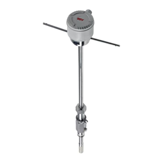
AquaProbe
FEA100/FEA200
flow sensor
The AquaProbe FEA100/FEA200 flow
sensor is designed for measurement of the
velocity of water. The flow sensor is
available in four standard lengths and can
be installed in any pipeline of internal
diameter from 200 mm (8 in.) to 8000 mm
(360 in.), through a small tapping.
The flow sensor is designed for use in
survey applications such as leakage
monitoring and network analysis and in
permanent locations where cost or space
limitations preclude the use of conventional
closed pipe meters.
This User Guide provides installation,
connection, security, start-up and basic
setup details for the flow sensor only. The
AquaProbe sensor is available for operation
with either a WaterMaster transmitter
(FET100) or an AquaMaster3 transmitter
(FET200).
Maximum performance,
minimum hassle
Measurement made easy
For more information
Further publications are available for free
download from
www.abb.com/flow
scanning this code:
Search for or click on
Data Sheet
AquaProbe FEA200
Insertion-type electromagnetic
flow sensor with AquaMaster3
transmitter
Data Sheet
AquaProbe FEA100
Insertion-type electromagnetic
flow sensor with WaterMaster
transmitter
or by
DS/FEA200-EN
DS/FEA100-EN
Advertisement
Table of Contents

Related Manuals for ABB AquaProbe FEA100


Summary of Contents for ABB AquaProbe FEA100
- Page 1 Measurement made easy — Introduction For more information AquaProbe FEA100/FEA200 flow sensor The AquaProbe FEA100/FEA200 flow Further publications are available for free sensor is designed for measurement of the download from www.abb.com/flow or by velocity of water. The flow sensor is...
- Page 2 Electromagnetic flowmeter | PROFIBUS RS485 Physical Layer (FEX100-DP) IM/WMPBST-EN User Guide Supplement WaterMaster Electromagnetic flowmeter | PROFIBUS FEX100-DP parameter tables ScrewDriver profiling and configuration software Search for or click on IM/SDR User Guide ScrewDriver 7 Diagnostic and Flow-Profiling Software for ABB Flowmeters...
-
Page 3: Table Of Contents
AquaProbe FEA100 / FEA200 Electromagnetic flowmeter – insertion-type flow sensors Safety ............................... 3 Health & Safety ........................3 Electrical Safety – CEI/IEC 61010-1:2001-2 ................3 Symbols – CEI/IEC 61010-1:2001-2 ..................3 Product Recycling Information ((European customers only) ............4 Information on ROHS Directive 2011/65/EU (RoHS II) .............. 5 Chemical Reagents ......................... - Page 4 AAquaProbe FEA100 / FEA200 Electromagnetic flowmeter – insertion-type flow sensors Appendix A ............................27 Velocity Profiles Background ....................27 Testing the Flow Profile for Symmetry ..................29 A.2.1 Partial Velocity Traverse ....................29 A.2.2 Single Entry Point Method .................... 29 A.2.3 Dual Entry Point Method ....................
-
Page 5: Safety
AquaProbe FEA100 / FEA200 Electromagnetic flowmeter – insertion-type flow sensors 1 Safety 1 Safety Information in this manual is intended only to assist our customers in the efficient operation of our equipment. Use of this manual for any other purpose is specifically prohibited and its contents are not to be reproduced in full or part without prior approval of the Technical Publications Department. -
Page 6: Product Recycling Information ((European Customers Only)
1.4 Product Recycling Information ((European customers only) ABB is committed to ensuring that the risk of any environmental damage or pollution caused by any of its products is minimized as far as possible. The European Waste Electrical and Electronic Equipment (WEEE) Directive that initially came into force on August 13 2005 aims to reduce the waste arising from electrical and electronic equipment;... -
Page 7: Information On Rohs Directive 2011/65/Eu (Rohs Ii)
1 Safety 1.5 Information on ROHS Directive 2011/65/EU (RoHS II) ABB, Industrial Automation, Measurement & Analytics, UK, fully supports the objectives of the ROHS II directive. All in-scope products placed on the market by IAMA UK on and following the 22nd of July 2017 and without any specific exemption, will be compliant to the ROHS II directive, 2011/65/EU. -
Page 8: Safety Conventions
1.10 Service and Repairs None of the instrument's components can be serviced by the user. Only personnel from ABB or its approved representative(s) is (are) authorized to attempt repairs to the system and only components formally approved by the manufacturer should be used. -
Page 9: System Schematic
AquaProbe FEA100 / FEA200 Electromagnetic flowmeter – insertion-type flow sensors 2 System Schematic 2 System Schematic AquaMaster3 FET200 WaterMaster FET100 Transmitter Transmitter AquaMaster 3 Flow Sensor Fig. 2.1 System Schematic Caution. Care of the Equipment The tip of the flow sensor is a precision-built part of the equipment and must be handled with care. -
Page 10: Mechanical Installation
AquaProbe FEA100 / FEA200 Electromagnetic flowmeter – insertion-type flow sensors 3 Mechanical Installation 3 Mechanical Installation 3.1 Location – Environmental Conditions 60 °C (140 °F) Maximum –20 °C (–4 °F) Minimum A – Within Temperature Limits 10 m (30 ft) -
Page 11: Use
AquaProbe FEA100 / FEA200 Electromagnetic flowmeter – insertion-type flow sensors 3 Mechanical Installation 3.2 Use An insertion probe is inserted into a flow-line through a small tapping and a valve fitted to the line. The tapping can be as small as one inch BSP or larger. Such a tapping is common on pipelines and, if one does not exist where it is required to make the installation, it is very inexpensive to fit one, online and under pressure, and there are many specialist companies that do this type of work. -
Page 12: Location - Flow Conditions
AquaProbe FEA100 / FEA200 Electromagnetic flowmeter – insertion-type flow sensors 3 Mechanical Installation 3.3 Location – Flow Conditions The flow sensor can be installed in one of two positions in the pipe: on the centre line at the mean axial velocity point ( pipe diameter) It can also be traversed across the pipe to determine the velocity profile. -
Page 13: International Standard For Flow Measurement
AquaProbe FEA100 / FEA200 Electromagnetic flowmeter – insertion-type flow sensors 3 Mechanical Installation 3.3.1 International Standard for Flow Measurement ISO 7145 '(BS 1042) Measurement of fluid flow in closed conduits 'Part 2 Velocity area methods' describes methods of calculating volumetric flow from velocity measurements. - Page 14 AquaProbe FEA100 / FEA200 Electromagnetic flowmeter – insertion-type flow sensors 3 Mechanical Installation Effective Probe Length Insertion Length Fig. 3.3 Maximum Permissible Velocity for Different Pipe Sizes It is important to add the external length from the fixing point to the insertion length. Failure to do this can give incorrect information from the graphs, resulting in vortex shedding affecting AquaProbe.
-
Page 15: Location - Mechanical
AquaProbe FEA100 / FEA200 Electromagnetic flowmeter – insertion-type flow sensors 3 Mechanical Installation 3.4 Location – Mechanical Note. Pipeline recommended to be metal for electrical screening. Dimensions in mm (in.) 320 (12.5) Ø104 (4.1) Transmitter terminal box manufactured before Q3 2014 Ø104 (4.1) -
Page 16: Safety
AquaProbe FEA100 / FEA200 Electromagnetic flowmeter – insertion-type flow sensors 3 Mechanical Installation 3.5 Safety Warning. The flow sensor is provided with a safety mechanism (see Fig. 3.6 A) that must be attached to its securing collar as shown in Fig. 3.6 B. This prevents rapid outward movement by the flow sensor if is released. -
Page 17: Installing The Flow Sensor
AquaProbe FEA100 / FEA200 Electromagnetic flowmeter – insertion-type flow sensors 3 Mechanical Installation 3.6 Installing the Flow Sensor Warning. When inserting or removing the flow sensor suitable restraining equipment must be used to prevent the flow sensor being forced out under pressure. Ensure that the valve is fully open. -
Page 18: Setting The Insertion Depth
AquaProbe FEA100 / FEA200 Electromagnetic flowmeter – insertion-type flow sensors 3 Mechanical Installation 3.7 Setting the Insertion Depth 3.7.1 Centre Line Method for Pipe Diameters 1 m (40 in.) Warning. When inserting or removing the flow sensor suitable restraining equipment must be used to prevent the flow sensor being forced out under pressure. -
Page 19: Centre Line Method For Pipe Diameters >1 M 2 M (>40 In 80 In.)
AquaProbe FEA100 / FEA200 Electromagnetic flowmeter – insertion-type flow sensors 3 Mechanical Installation 3.7.2 Centre Line Method for Pipe Diameters >1 m 2 m (>40 in 80 in.) Warning. When inserting or removing the flow sensor, suitable restraining equipment must be used to prevent the flow sensor being forced out under pressure. -
Page 20: Mean Axial Velocity Method
AquaProbe FEA100 / FEA200 Electromagnetic flowmeter – insertion-type flow sensors 3 Mechanical Installation 3.7.3 Mean Axial Velocity Method Warning. When inserting or removing the flow sensor suitable restraining equipment must be used to prevent the flow sensor being forced out under pressure. Ensure that the valve is fully open. -
Page 21: Flow Sensor Alignment
AquaProbe FEA100 / FEA200 Electromagnetic flowmeter – insertion-type flow sensors 3 Mechanical Installation 3.8 Flow Sensor Alignment Warning. When inserting or removing the flow sensor suitable restraining equipment must be used to prevent the flow sensor being forced out under pressure. Ensure that the valve is fully open. -
Page 22: Electrical Installation
AquaProbe FEA100 / FEA200 Electromagnetic flowmeter – insertion-type flow sensors 4 Electrical Installation 4 Electrical Installation 4.1 Sensor Terminal Box Connections – WaterMaster FET100 Transmitter Caution. Make connections only as shown. Remove foil screens Twist the three screen wires together and sleeve them. -
Page 23: Environmental Protection
AquaProbe FEA100 / FEA200 Electromagnetic flowmeter – insertion-type flow sensors 4 Electrical Installation 4.2 Environmental Protection Fig. 4.2 Potting the Terminal Box – WaterMaster FET1 Transmitter Warning. Potting materials are toxic – use suitable safety precautions. Read the manufacturers instructions carefully before preparing the potting material. -
Page 24: Setting Up
AquaProbe FEA100 / FEA200 Electromagnetic flowmeter – insertion-type flow sensors 5 Setting Up 5 Setting Up 5.1 Introduction The basic equation for volume measurement using the flow sensor is: Where: Q = flow rate insertion factor profile factor velocity area The profile factor and insertion factor must be determined as detailed in Section 5.2 to 5.3, page 23 as... -
Page 25: Mean Axial Velocity Method (1/8 Diameter)
AquaProbe FEA100 / FEA200 Electromagnetic flowmeter – insertion-type flow sensors 5 Setting Up 5.3 Mean Axial Velocity Method ( Diameter) 1. Determine the internal diameter D of the pipe, in millimeters, by the most accurate method available. 2. A profile factor F of 1 must be used. -
Page 26: Specification
AquaProbe FEA100 / FEA200 Electromagnetic flowmeter – insertion-type flow sensors 6 Specification 6 Specification FEA100/FEA200 Flow Sensor Maximum insertion length 300mm (12 in.) 500mm (20 in.) 700mm (25 in.) 1000mm (40 in.) Pipe sizes 200 to 8000 mm (8 to 320 in.) nominal bore Protection IP68/NEMA 6P (Indefinite submersion down to 10 m [30 ft.]) - Page 27 AquaProbe FEA100 / FEA200 Electromagnetic flowmeter – insertion-type flow sensors 6 Specification Maximum Flow The maximum velocity depends upon the actual insertion length. Typical insertion lengths are 0.125 and 0.5 x pipe diameter. The graph is a guide* to the maximum allowable velocity for different insertion lengths.
- Page 28 AquaProbe FEA100 / FEA200 Electromagnetic flowmeter – insertion-type flow sensors 6 Specification Limits of Upstream Disturbance Diameters Table Below Centre Line Minimum Upstream Straight Length* Type of Disturbance Upstream from the Measuring Cross-Section For a measurement at the point of...
-
Page 29: Velocity Profiles Background
AquaProbe FEA100 / FEA200 Electromagnetic flowmeter Appendix A A.1 Velocity Profiles Background Fig. A.1 on page 27 is a vector diagram showing a fully developed turbulent profile of the flow within a pipe. Such diagrams illustrate the distribution of flow within the pipe. Known as the Flow Profile, it is highest in the centre falling to zero at either side on the pipe wall. - Page 30 AquaProbe FEA100 / FEA200 Electromagnetic flowmeter The Point of Mean Velocity is on the knee of the curve (the velocity at this point is changing rapidly with distance) so it is necessary to position the probe extremely accurately in order to measure the correct velocity.
-
Page 31: Testing The Flow Profile For Symmetry
AquaProbe FEA100 / FEA200 Electromagnetic flowmeter When the probe insertion position is determined, the effect of putting the probe into the pipe (see Section 3.3.2, page 11) must be calculated. The blockage or insertion effect is termed the Insertion Factor (Fi). This is a mathematical relationship and... -
Page 32: Dual Entry Point Method
For installations with very poor and asymmetric velocity profiles (for example as rejected in Section A.2.2, page 29) a full velocity profile provides an improved accuracy of reading. To facilitate this ABB have developed ScrewDriver software for the PC that calculates F and F for any measured velocity profile –... -
Page 33: Appendix B - Measuring The Internal Diameter
(performed on ABB's UKAS-approved and traceable flow rigs in the UK) compensates for small deviations in size. In the case of a probe, clearly it can't be tested in the pipe in which it is to be finally installed. It is therefore not possible to take account of the difference between the nominal or expected internal diameter of the pipe and its actual value. -
Page 34: Notes
AquaProbe FEA100 / FEA200 Electromagnetic flowmeter Notes OI/FEA100/200–EN Rev. D... - Page 35 Acknowledgments • Modbus is a registered trademark of Schneider Electric USA Inc. • PROFIBUS is a registered trademark of PROFIBUS organization. Sales Service...
- Page 36 We reserve all rights in this document and in the subject matter and illustrations contained therein. Any reproduction, disclosure to third parties or utilization of its contents – in whole or in parts – is forbidden without prior written consent of ABB. © ABB 2018...
Need help?
Do you have a question about the AquaProbe FEA100 and is the answer not in the manual?
Questions and answers