Advertisement
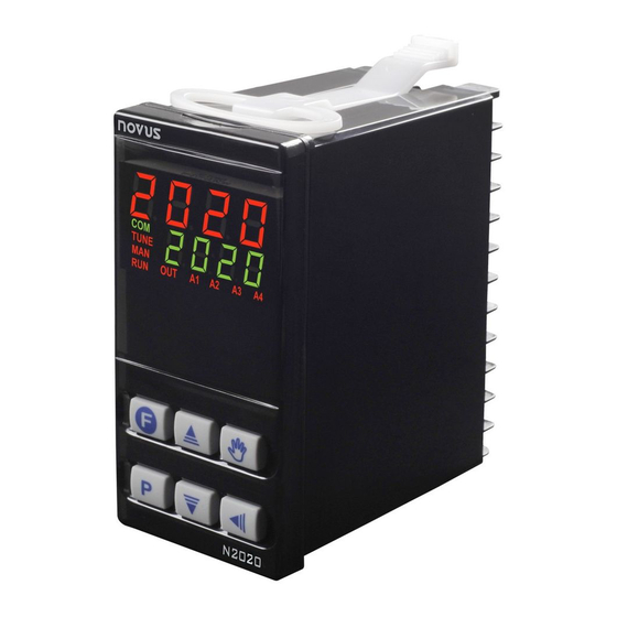
N2020 Controller
TEMPERATURE CONTROLLER – INSTRUCIONS MANUAL – V1.0x D
SAFETY ALERTS
The symbols below are used on the equipment and throughout this
document to draw the user's attention to important operational and
safety information.
CAUTION:
Read the manual thoroughly
before installing and
operating the equipment.
All safety related instructions that appear in the manual must be
observed to ensure personal safety and to prevent damage to either
the instrument or the system. If the instrument is used in a manner not
specified by the manufacturer, the protection provided by the
equipment may be impaired.
INSTALLATION / CONNECTIONS
The controller must be fastened on a panel, following the sequence
of steps described below:
• Prepare a panel cut-out of 45 x 93 mm;
• Remove the mounting clamps from the controller;
• Insert the controller into the panel cut-out;
• Slide the mounting clamp from the rear to a firm grip at the panel.
ELECTRICAL CONNECTIONS
The controller complete set of features is drawn in Fig. 01:
Fig. 01 - Input connections, outputs and power supply
NOVUS AUTOMATION
CAUTION OR DANGER:
Electrical shock hazard
RECOMMENDATIONS FOR THE INSTALLATION
• Leads of input signals may travel the plant, separately of output
and feeding leads, if is possible in grounded conduits.
• All electronic instruments must be powered by a clean mains
supply, proper for instrumentation.
• It is strongly recommended to apply RC'S FILTERS (noise
suppressor) to contactor coils, solenoids, etc.
FEATURES
INPUT TYPE SELECTION
The input type to be used by the controller is defined in the
equipment settings. Table 01 shows the input options available for
the user, one of them must be selected during the controller setting.
TYPE
CODE
Thermocouple J
Range: -110 to 950 °C (-166 to 1742 °F)
Tc j
Thermocouple K
Range: -150 to 1370 °C (-238 to 2498 °F)
Tc k
Thermocouple T
Range: -160 to 400 °C (-256 to 752 °F)
Tc t
Pt100
Range: -200 to 850 °C (-328 to 1562 °F)
Pt
Table 01 – Inputs types
Fig. 02 - Connection of
thermocouple
Notes:
1- The specification of controller accuracy does not consider the
error showed by the temperature sensor used.
2- Suitable extension cables must be used with thermocouples.
3- In order to use 2-wire Pt100 thread, connect 23 and 24 terminals.
The sensor must be connected between 22 and 23 terminals. If
the sensor is 4-wired, keep one of the wires disconnected close to
the controller. The wires used must always have the same section
(same gauge).
OUTPUTS
The controller offers two, three or four output channels, depending on
the loaded optional features. Those channels are configured by the
user to act as control outputs, alarm outputs, LBD Function or PV or
SP retransmission.
OUT1 -
Logical pulse, 5 Vdc / 25 mA
Available at terminals 19 and 20 of controller
OUT2 -
Relay SPST-NA
Available at terminals 17 and 18 of controller
OUT3 -
Relay SPST-NA
Available at terminals 15 and 16 of controller
RANGE OF MEASUREMENT
Fig. 03 - Connection of 3-wires
Pt100
1/7
Advertisement
Table of Contents

Related Manuals for Novus N2020


Summary of Contents for Novus N2020
- Page 1 N2020 Controller TEMPERATURE CONTROLLER – INSTRUCIONS MANUAL – V1.0x D SAFETY ALERTS RECOMMENDATIONS FOR THE INSTALLATION • Leads of input signals may travel the plant, separately of output The symbols below are used on the equipment and throughout this and feeding leads, if is possible in grounded conduits.
-
Page 2: Alarm Output
N2020 Controller OUT4 - Analog output: Alarms turned off. Electrical current, 0-20 mA or 4-20 mA Electrical voltage pulse, 10 Vdc / 20 mA Alarm of Absolute Minimum Value. Triggers when the Available at 29 and 30 terminals of controller... -
Page 3: Operation
N2020 Controller LBD – LOOP BREAK DETECTION The program created is storage permanently on the controller’s ram. It may be always changed, executed and repeated whenever The parameter defines a time interval, in minutes, within which the necessary. PV is expect to react to a control output signal. If the PV does not For the program’s execution:... -
Page 4: Description Of The Parameters
N2020 Controller OUT indicator: It shows the instantaneous state of the controller TUNING CYCLE output(s). Auto-Tune: Enables the auto-tuning function for the Atvn A1 and A2 indicator: signalize the occurrence of alarm situation. PID parameters (pb,ir, dt). Refer PID Parameters... - Page 5 N2020 Controller PROGRAMS CYCLE Unit. Defines the temperature unit to be used: vni t Indication in Celsius. Program Tolerance - Maximum admitted deviation of Ptol PV with respect to SP. If exceeded, the program Indication in Fahrenheit. execution is suspended (the internal timer freezes) until Offset.
-
Page 6: Configuration Protection
Controller serial number is displayed by pressing for 5 seconds. CALIBRATION OF THE INPUT Visit our web site for further information www.novusautomation.com. IDENTIFICATION N2020 - PRR Basic version. Three outputs. OUT1= pulse / OUT2= relay / OUT3= relay N2020 - PRRA For outputs. -
Page 7: Specifications
LIABILITY DIMENSIONS: ..........48 x 96 x 92 mm (1/8 DIN) NOVUS warrants to the original purchaser that this product is free from Approximate:................. 180 g defects in material and workmanship under normal use and service POWER SUPPLY: ......100 to 240 Vac (± 10 %), 50/60 Hz within one (1) year from the date of shipment from factory or from its ..............
Need help?
Do you have a question about the N2020 and is the answer not in the manual?
Questions and answers