Table of Contents
Advertisement
Quick Links
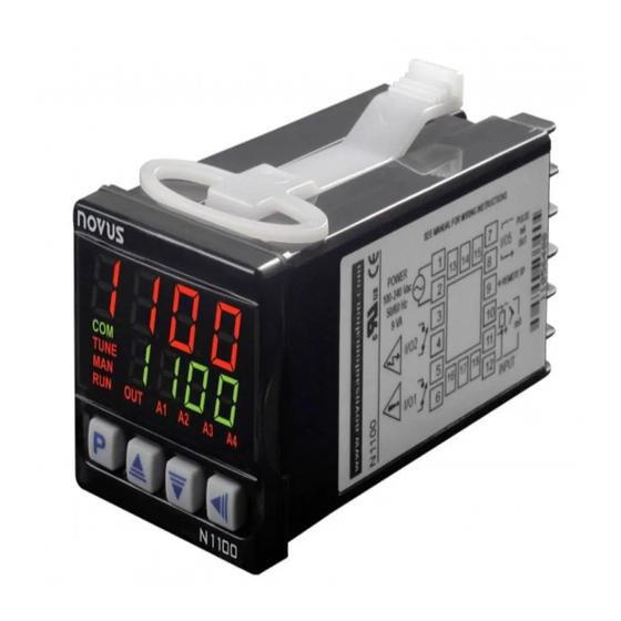
Controller N1100
UNIVERSAL CONTROLLER – INSTRUCTIONS MANUAL – V4.0x D
SAFETY ALERTS
The symbols below are used on the equipment and throughout this
document to draw the user's attention to important operational and
safety information.
CAUTION:
Read complete instructions prior to
installation and operation of the
unit.
All safety related instructions that appear in the manual must be
observed to ensure personal safety and to prevent damage to either
the instrument or the system. If the instrument is used in a manner not
specified by the manufacturer, the protection provided by the
equipment may be impaired.
PRESENTATION
The N1100 is an extraordinarily versatile process controller. It holds
in one single instrument all the main features needed for the vast
majority of industrial processes. It accepts in a single model virtually
all the sensors and signals used in the industry and provides the
main output types required for the operation of diverse processes.
The configuration can be performed directly on the controller or through
the USB interface. The NConfig software (free) is the configuration
management tool. Connected to the USB of a Windows computer, the
controller is recognized as a serial communications port (COM) running
with a Modbus RTU protocol.
Through the USB interface, even if disconnected from the power
supply, the configuration performed in a piece of equipment can be can
be saved in a file and repeated in other pieces of equipment that
require the same configuration.
It is important that the users read carefully this manual before using
the controller. Verify if the release of this manual matches the
instrument version (the firmware version is shown when the controller
is energized).
MAIN CHARACTERISTICS
• Multi-sensor universal input (sensors and standard signals);
• Protection for open sensor in any condition;
• Relay, 4-20 mA and logic pulse control outputs all available in the
standard model;
• Self-tuning of PID parameters;
• Automatic / Manual function with "bumpless" transfer;
• Four modes of independents alarms, with functions of minimum,
maximum, differential (deviation), open sensor and event;
• Timer functions that can be associated to the alarms;
• Retransmission of PV or SP in 0-20 mA or 4-20 mA;
• Input for remote setpoint;
• Digital input with 5 functions;
• Programmable soft-start;
• 7 setpoint profile programs with 7 segments each, with the ability
to be linked together for a total of 49 segments;
• Password for parameters protection;
• Universal power supply.
NOVUS AUTOMATION
CAUTION OR WARNING:
Electrical shock hazard.
CONFIGURATION / FEATURES
Select the input type (in parameter "tYPE") from Table 1 below
TYPE
CODE
CHARACTERISTICS /
J
Range: -110 to950 ºC (-166to 1742 ºF)
Tc j
K
Range: -150 to 1370 ºC (-238to 2498 ºF)
Tc k
T
Range: -160 to 400 ºC (-256to 752 ºF)
Tc t
N
Range: -270 to 1300 ºC (-454to 2372 ºF)
Tc n
R
Range: -50to 1760 ºC (-58to 3200 ºF)
Tc r
S
Range: -50to 1760 ºC (-58to 3200 ºF)
Tc s
B
Range: 400to 1800 ºC (752to 3272 ºF)
Tc b
E
Range: -90to 730ºC (-130to1346 ºF)
Tc e
Pt100
Range: -200to850ºC (-328to1562ºF)
Pt
0–50 mV
L. 0 . 5 0
Linear Signals
4-20 mA
L. 4 . 2 0
Programmable indication from-1999 to 9999
0-5 Vdc
L0. 5
4-20 mA input with Square Root extraction.
4-20 mA
sqrt
Programmable indication from-1999 to 9999
ln j
Ln k
ln t
ln n
4-20 mA
Non Linear Analog Signals
NON
ln r
Indication range depends on the selected sensor
LINEAR
ln s
ln b
ln E
Ln. P t
Table 1 – Input types
Note: All input types are factory calibrated.
OUTPUTS, ALARMS AND DIGITAL INPUTS CONFIGURATION
The controller input and output channels (I / O) can assume multiple
functions: control output, digital input, digital output, alarm output,
retransmission of PV and SP. These channels are identified as I / O
1, I / O 2, I / O 3, I / O 4 and I / O 5.
The basic controller model comes loaded with the following features:
I / O 1- output to Relay SPST-NA;
I / O 2- output to Relay SPST-NA;
I / O 5- current output, digital output, digital input;
Optionally, other features can be added, as shown under the item
"Identification" in this manual:
- 3R:
I / O3 with output to SPDT relay;
- DIO: I / O3 and I / O4 as digital input and output channels;
- 485:
Serial Communication
RANGE OF MEASUREMENT
1/11
Advertisement
Table of Contents

Related Manuals for Novus N1100


Summary of Contents for Novus N1100
- Page 1 PRESENTATION Programmable indication from-1999 to 9999 0-5 Vdc L0. 5 The N1100 is an extraordinarily versatile process controller. It holds 4-20 mA input with Square Root extraction. 4-20 mA sqrt in one single instrument all the main features needed for the vast Programmable indication from-1999 to 9999 majority of industrial processes.
-
Page 2: Alarms Functions
N1100 Controller The function code of each I/O can be selected among the options on Pr 1 – Digital input with function to Execute Program 1 • Table 2. Defines the channel as Digital Input with the function of commanding the execution of the setpoing profile program 1. -
Page 3: Alarm Initial Blocking
N1100 Controller SQUARE ROOT EXTRACTION PROMPT TYPE ACTION Disabled Output is not used as alarm. When the input type is configured as SQRT the controller assumes the input as a 4-20 mA while extracting the square root of the applied... -
Page 4: Usb Interface
N1100 Controller USB INTERFACE ELECTRICAL CONNECTIONS The USB interface is used for CONFIGURING or MONITORING the The controller complete set of features is drawn in Figure 1: controller. The NConfig software must be used for the configuration. It makes it possible to create, view, save and open configurations from the equipment or files in your computer. -
Page 5: Operation
N1100 Controller Remote Setpoint A1, A2, A3 and A4 indicators: signalize the occurrence of alarm situation. Feature available in the controller's terminals 9 and 10. When the Remote SP input signal is 0-20 mA or 4-20 mA, an external P Key used to walk through the menu parameters. -
Page 6: Description Of The Parameters
N1100 Controller DESCRIPTION OF THE PARAMETERS Control logic: Control with reverse Action. Appropriate for Action PV / SP indication - The upper display shows the PV Indication heating. Turns control output on when PV is (Red Screen) current value of PV. The lower display shows the below SP. -
Page 7: Calibration Cycle
N1100 Controller CYCLE OF ALARMS Defines the signal type for the remote SP. Functions of Alarms. Defines the functions for the 0-20 current of 0-20 mA Remote SP Fva1 alarms among the options of the Table 3. 4-20 current of 4-20 mA... -
Page 8: Protection Of Configuration
N1100 Controller See section: MAINTENANCE / Input Calibration. Parameter that informs the controller about the rsL( ktyp hardware optionals installed. It should not be altered Enter the value corresponding to the low scale Remote SP Low Hardware Type by the user, except when an accessory is introduced signal applied to the remote SP input. -
Page 9: Programs Of Ramp And Soak
N1100 Controller The master password is made up by the last three digits of the serial 1. If PtoL is different than zero, the controller will wait for the PV to number of the controller added to the number 9000. -
Page 10: Analog Output Calibration
“ovLC” to indicate this current value (use the Follows a description of the usual communication registers. For full keys) documentation download the Registers Table for Serial Communication in the N1100 section of our web site – • Select the screen “ovxC”. Press the keys for the www.novusautomation.com. -
Page 11: Specifications
0.170 mA. NOVUS liability under this warranty shall not in any case exceed the All input and output types are factory-calibrated. Thermocouples cost of correcting defects in the product or of supplying replacement according to standard NBR 12771 / 99, RTD’s NBR 13773 / 97;...
Need help?
Do you have a question about the N1100 and is the answer not in the manual?
Questions and answers