Table of Contents
Advertisement
Quick Links
Advertisement
Table of Contents

Related Manuals for Novus N2000S


Summary of Contents for Novus N2000S
- Page 1 N2000S CONTROLLER USER GUIDE V3.0x C...
-
Page 2: Table Of Contents
FEATURES ..................................22 10.2 SERIAL COMMUNICATION CONFIGURATION ......................22 PROBLEMS WITH THE CONTROLLER ............................23 SPECIFICATIONS ..................................24 WARRANTY ....................................25 ATTACHMENT 1 – COMMUNICATION PROTOCOL ........................26 14.1 COMMUNICATION INTERFACE ..........................26 14.2 RS485 INTERFACE ..............................26 NOVUS AUTOMATION 2/38... - Page 3 14.3 GENERAL FEATURES ..............................26 14.4 COMMUNICATION PROTOCOL ..........................26 14.4.1 SETTING THE COMMUNICATION PARAMETERS ..................26 14.4.2 REGISTER TABLE ............................27 14.4.3 STATUS WORDS ............................36 14.5 EXCEPTION RESPONSES – ERROR CONDITIONS ....................38 NOVUS AUTOMATION 3/38...
-
Page 4: Safety Summary
All safety related instructions that appear in the manual must be observed to ensure personal safety and to prevent damage to either the instrument or the system. If the instrument is used in a manner not specified by the manufacturer, the protection provided by the equipment may be impaired. NOVUS AUTOMATION 4/38... -
Page 5: Introduction
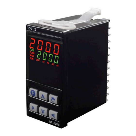
INTRODUCTION N2000S is a controller for servo positioners with two control relays: one to open and other to close the valve (or damper). Moreover, it has an analog output that can be programmed to control or retransmit input or setpoint signals. Its universal input accepts most industry manufactured sensors and signals. -
Page 6: Operation
All parameters set up are stored in a protected memory. Changed values are automatically saved when the user goes to the next parameter. The SP value is saved when parameters are changed or at every 25 seconds. NOVUS AUTOMATION 6/38... -
Page 7: Configuration Protection
If the calculated output is between 0 % or 100 % and it is maintained for some time, the opening relay (when in 0 %) or the closing relay (when in 100 %) will be periodically activated for a time fraction to assure that the real position is close to the estimated position, for mechanical problems or non-linearity of the process. NOVUS AUTOMATION 7/38... -
Page 8: Configuration / Resources
Defines channel as alarm 1. Defines channel as alarm 2. 4.2.2 I/O 3 AND I/O4 – USED AS CONTROL OUTPUTS 2 SPST relays, available in terminals 3 to 6. They are assigned code 5. Where: Defines channel as control output NOVUS AUTOMATION 8/38... -
Page 9: I/O 5 - Analog Output
Closed = Selects program 1. Open = Assumes the main Setpoint. Note: When a function is selected to operate through digital input, the controller does not respond to the equivalent function command given in the frontal keypad. NOVUS AUTOMATION 9/38... -
Page 10: Potentiometer Input
SV + SPAn SV - SPAn negative SPAn positive SPAn Table 3 SPAn refers to SPA and SPA2 alarm Setpoints. 4.4.5 MAXIMUM VALUE It triggers when the measured value is above the value set by the alarm Setpoint. NOVUS AUTOMATION 10/38... -
Page 11: Differential (Or Band)
SPLL and SPkL. To obtain voltage retransmission the user must install a shunt resistor (550 Ω max.) in the analog output terminal. The resistor value depends on the voltage range required. NOVUS AUTOMATION 11/38... -
Page 12: Key Functions
Closed = Selects program 1. Open = Assumes the main Setpoint. Note: When a function is selected to operate through digital input, the controller does not respond to the equivalent function command given in the frontal keypad. No function . NOVUS AUTOMATION 12/38... -
Page 13: Installation / Connections
(use conductors with the same gauge and length). In case the sensor has 4 wires, one should be left loose near the controller. For 2-wire Pt100, short circuit terminals 22 and 23 Figure 5 NOVUS AUTOMATION 13/38... -
Page 14: Alarm And Output Connection
When I/O channels are set up as output channels, they must have their capacity respected, according do specifications. Figure 8 Note: It is recommended to disable/suspend the control ( ) whenever it is necessary to change the device settings. NOVUS AUTOMATION 14/38... -
Page 15: Configuration Parameters
Alarm SP. Value that defines the trigger point of alarms programmed with the Lo or ki functions. Sp. a 1 In alarms programmed with the function Differential this parameter defines the deviation. Sp. a 2 It is not used in other alarm functions. Alarm Setpoint NOVUS AUTOMATION 15/38... -
Page 16: Program Cycle
Alarm 2 time 2. Defines the period in which alarm 2 will be off after being activated. Set zero to disable this function. Alarm 2 Table 4 shows the advanced functions one can obtain with timer. time 2 NOVUS AUTOMATION 16/38... -
Page 17: Input Configuration Cycle
Key function: Allows definition of the key function. Available functions: f. f vnc Key not used. Controls output and alarm outputs (RUN function). Invalid selection. Hold program execution. Selects program 1. These functions are described in FUNCTIONS. NOVUS AUTOMATION 17/38... -
Page 18: Calibration Cycle
Value for current output high calibration. Calibration Cold joint Offset calibration. (j l Parameter to adjust the cold joint temperature offset. Potentiometer low calibration. Potl To change one digit, press as many times as necessary. Calibration of the potentiometer's full scale. Potx NOVUS AUTOMATION 18/38... -
Page 19: Ramp And Soak Program
Start the control at the rvn screen. • Before executing the program, the controller waits for PV to reach the initial Setpoint (SP0). Should any power failure occur, the controller resumes at the beginning of the segment it was running. NOVUS AUTOMATION 19/38... -
Page 20: Pid Parameters Auto-Tuning
If the automatic tune does not result a satisfactory control, the table below guides how to correct the process behavior: PARAMETER PROBLEM SOLUTION Proportional Slow response Decrease band Large oscillation Increase Integral rate Slow response Increase Large oscillation Decrease Derivative time Slow response or Decrease instability Large oscillation Increase Table 6 NOVUS AUTOMATION 20/38... -
Page 21: Calibration
0.0 in the parameters display. 5. Adjust the potentiometer with the maximum value. 6. Access the Potk parameter. By using the keys, select 100.0 in the parameters display. 7. Repeat c to f up to no new adjustment is necessary. NOVUS AUTOMATION 21/38... -
Page 22: Serial Communication
Terminal 27 Table 7 10.2 SERIAL COMMUNICATION CONFIGURATION You must configure 2 parameters to use the serial: bavd: Communication speed. All equipment’s with the same speed. Addr: Controller communication address. Each controller must have an exclusive address. NOVUS AUTOMATION 22/38... -
Page 23: Problems With The Controller
If errors persist even after a review, contact the manufacturer. Also inform the device serial number. To find out the serial number, press for more than 3 seconds. The controller also has a visual alarm (the display flashes) when the PV value is out of the range set by spxl and spll. NOVUS AUTOMATION 23/38... -
Page 24: Specifications
PROPER CONNECTIONS FOR 6.3 MM PIN TYPE THERMINALS. FRONT PANEL: ................................IP65, polycarbonate UL94 V-2 HOUSING: ....................................IP20, ABS+PC UL94 V-0 CERTIFICATIONS: CE, UL and UKCA PROGRAMMABLE PWM CYCLE FROM 0.5 TO 100 SECONDS. AFTER POWER UP, IT STARTS OPERATION AFTER 3 SECONDS. NOVUS AUTOMATION 24/38... -
Page 25: Warranty
WARRANTY Warranty conditions are available on our website www.novusautomation.com/warranty. NOVUS AUTOMATION 25/38... -
Page 26: Attachment 1 - Communication Protocol
14.4.1 SETTING THE COMMUNICATION PARAMETERS To use the serial, you must set 2 parameters: bavd : Communication baud rate. All devices have the same baud rate. addr : Controller communication address. Each controller must have a unique address. NOVUS AUTOMATION 26/38... -
Page 27: Register Table
Reserved. PWM Cycle time (in seconds). 0015 Range: 5 to 1000 (0.5 to 100.0). 0016 PID output filter. SErF ON/OFF control hysteresis (in the unit of the selected type). 0017 kyst Range: 0 to spkl - spll. NOVUS AUTOMATION 27/38... - Page 28 Fva2 Range: Same as the fua1 screen. 0037 Reserved. 0038 Reserved. Alarm 1 hysteresis. 0039 Kya1 Range: 0 to 9999 (0.00 to 99.99 %). Alarm 2 hysteresis. 0040 Kya2 Range: 0 to 9999 (0.00 to 99.99 %). NOVUS AUTOMATION 28/38...
- Page 29 SErr Select whether the MV value shown on the display is the internally estimated value or the measured potentiometer position. Range: 0056 0 → Internal MV. 1 → Potentiometer. 0057 Reserved. 0058 Reserved. 0059 Reserved. 0060 Reserved. NOVUS AUTOMATION 29/38...
- Page 30 0088 Range: Same as the pe1 screen. Event from segment 3 of program 3 (R&S). 0089 Range: Same as the pe1 screen. Event from segment 4 of program 3 (R&S). 0090 Range: Same as the pe1 screen. NOVUS AUTOMATION 30/38...
- Page 31 Event from segment 2 of program 7 (R&S). 0116 Range: Same as the pe1 screen. Event from segment 3 of program 7 (R&S). 0117 Range: Same as the pe1 screen. 0118 Event from segment 4 of program 7 (R&S). NOVUS AUTOMATION 31/38...
- Page 32 Program 2 - Time 2. 0142 Range: 0 to 9999 minutes. Program 2 - Time 3. 0143 Range: 0 to 9999 minutes. Program 2 - Time 4. 0144 Range: 0 to 9999 minutes. 0145 Program 2 - Time 5. NOVUS AUTOMATION 32/38...
- Page 33 Range: Same as the psp0 screen. Program 3 - Setpoint 5 (Ramps and Soaks). 0170 Psp5 Range: Same as the psp0 screen. Program 3 - Setpoint 6 (Ramps and Soaks). 0171 Psp6 Range: Same as the psp0 screen. NOVUS AUTOMATION 33/38...
- Page 34 Range: 0 to 9999 minutes. Program 5 - Time 5. 0196 Range: 0 to 9999 minutes. Program 5 - Time 6. 0197 Range: 0 to 9999 minutes. Program 5 - Time 7. 0198 Range: 0 to 9999 minutes. NOVUS AUTOMATION 34/38...
- Page 35 Program 6 - Setpoint 7 (Ramps and Soaks). 0223 Psp7 Range: Same as the psp0 screen. Tolerance of program 7 (Ramps and Soaks). 0224 ptol Range: 0 to (spkl - spll) value. 0225 Program 7 Link (Ramps and Soaks). NOVUS AUTOMATION 35/38...
-
Page 36: Status Words
7 – Reserved bit 8 – Value to detect hardware bit 9 – Value to detect hardware bit 10 – Reserved bit 11 – Reserved bit 12 − Reserved bit 13 − Reserved bit 14 − Reserved NOVUS AUTOMATION 36/38... -
Page 37: Output Description
You can only write to the digital output bits when the outputs are set to OFF in the controller I/O configuration. COIL STATUS OUTPUT DESCRIPTION Output 1 status (I/O1) Output 2 status (I/O2) Output 3 status (I/O3) Output 4 status (I/O4) Output 5 status (I/O5) Table 12 NOVUS AUTOMATION 37/38... -
Page 38: Exception Responses - Error Conditions
The controller ignores the read commands in Broadcast. That is, there will be no response. You can only write in Broadcast mode. ERROR CODES ERROR DESCRIPTION Invalid or non-existent command. Register number invalid or out of range. Number of registers invalid or out of range. Table 13 NOVUS AUTOMATION 38/38...
Need help?
Do you have a question about the N2000S and is the answer not in the manual?
Questions and answers