Table of Contents
Advertisement
Quick Links
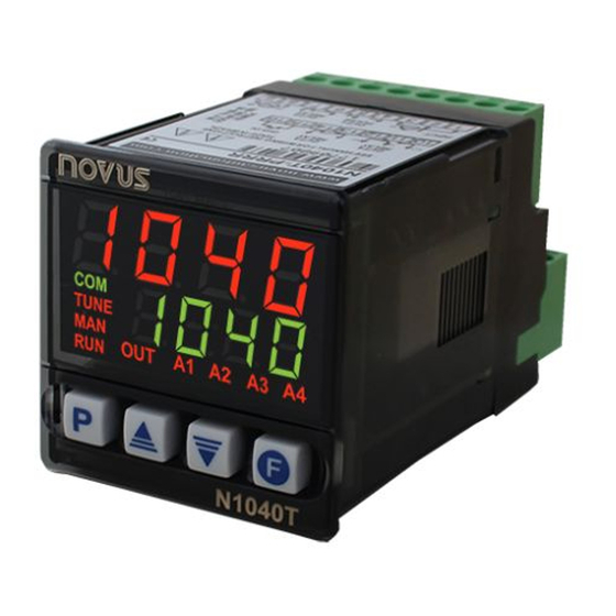
N1040T Controller
TEMPERATURE CONTROLLER AND TIME – INSTRUCTIONS MANUAL
SAFETY ALERTS
The symbols below are used on the equipment and throughout this
document to draw the user's attention to important operational and
safety information.
CAUTION:
Read the manual thoroughly
before installing and operating
the equipment.
All safety related instructions that appear in the manual must be
observed to ensure personal safety and to prevent damage to either
the instrument or the system. If the instrument is used in a manner not
specified by the manufacturer, the protection provided by the
equipment may be impaired.
INSTALLATION / CONECTIONS
The controller must be fastened on a panel, following the sequence
of steps described below:
• Prepare a panel cut-out of 46 x 46 mm;
• Remove the mounting clamps from the controller;
• Insert the controller into the panel cut-out;
• Slide the mounting clamp from the rear to a firm grip at the panel.
ELECTRICAL CONNECTIONS
Fig. 01 below shows the electrical terminals of the controller:
Fig. 01 - Connections of the back panel
NOVUS AUTOMATION
CAUTION OR DANGER:
Electrical shock hazard
– V2.1x D
RECOMMENDATIONS FOR THE INSTALLATION
• All electrical connections are made to the screw terminals at the
rear of the controller.
• To minimize the pick-up of electrical noise, the low voltage DC
connections and the sensor input wiring should be routed away
from high-current power conductors. If this is impractical, use
shielded cables. In general, keep cable lengths to a minimum.
• All electronic instruments must be powered by a clean mains
supply, proper for instrumentation.
• It is strongly recommended to apply RC'S FILTERS (noise
suppressor) to contactor coils, solenoids, etc. In any application it
is essential to consider what can happen when any part of the
system fails. The controller features by themselves can not assure
total protection.
FEATURES
INPUT TYPE SELECTION
Table 01 shows the sensor types accepted and their respective
codes and ranges. Access the parameter TYPE
to select the appropriate sensor.
TYPE
CODE
Thermocouple J
Tc j
Tc j
Range: -110 to 950 °C (-166 to 1742 °F)
Tc j
Tc j
Thermocouple K Tc k
Range: -150 to 1370 °C (-238 to 2498 °F)
Tc k
Tc k
Tc k
Thermocouple T
Range: -160 to 400 °C (-256 to 752 °F)
Tc t
Tc t
Tc t
Tc t
Pt100
Range: -200 to 850 °C (-328 to 1562 °F)
Pt
Pt
Pt
Pt
Table 01 – Input types
DIGITAL INPUT (DIG IN)
Available at terminals 15th and 16th on the back panel of the
controller. Detects the closing of dry contact switches.
The
A3
indicator
lamp
Digital Input:
On
= DI Actioned (contact closed)
Off
= DI Not Actioned (contact open)
OUTPUTS
The controller offers two or four output channels, depending on the
loaded optional features. The output channels are user configurable
as Control Output, Output Timers (T1), Output Timers (T2),
Alarm Output 4.
OUT1 - Logical pulse, 5 Vdc / 25 mA, available at terminals 4 and 5
of the controller.
OUT2 - Relay SPST-NA. Available at terminals 6 and 7.
OUT3 - Relay SPST-NA. Available at terminals 13 and 14.
OUT4 - Relay SPDT, available at terminals 10, 11 and 12.
TEMPERATURE CONTROL OUTPUT
The process control output can operate in ON/OFF mode or in PID
mode. To operate in ON/OFF, mode the value defined in the
parameter PB
PB
PB
PB should be 0.0. The control strategy can be ON/OFF
(when PB
PB
PB = 0.0) or PID. The PID parameters can be automatically
PB
determined enabling the auto-tuning function (ATvN
TYPE in the INPUT cycle
TYPE
TYPE
RANGE OF MEASUREMENT
shows
the
condition
of
ATvN).
ATvN
ATvN
the
1/7
Advertisement
Table of Contents

Related Manuals for Novus N1040T


Summary of Contents for Novus N1040T
- Page 1 N1040T Controller TEMPERATURE CONTROLLER AND TIME – INSTRUCTIONS MANUAL – V2.1x D SAFETY ALERTS RECOMMENDATIONS FOR THE INSTALLATION The symbols below are used on the equipment and throughout this • All electrical connections are made to the screw terminals at the document to draw the user’s attention to important operational and...
- Page 2 N1040T Controller ALARM OUTPUT This function allows the user to detect problems in the installation, for example an actuator with a defect, a failure of supply power, etc. The controller has an alarm that can be configured to operate on any of the output channels.
- Page 3 N1040T Controller DOWN mode, the display starts showing the time setting and counts TIMERS down to zero. This controller contains two timers that can operate independently of the control output. TEMPERATURE CONTROL OUTPUT DURING TIMER OPERATION T1 TIMER During the T1 and T2 operation the control output works normally.
- Page 4 N1040T Controller The “P” key is used for accessing the parameters within a level. kyst kyst kyst kyst Control hysteresis: Is the hysteresis for ON/OFF Keeping the “P” key pressed, at every 2 seconds the controller jumps control (set in temperature units). This parameter is...
- Page 5 N1040T Controller CALIBRATION CYCLE Time base for the timers T1 and T2. tbas tbas tbas tbas All types of input are calibrated in the factory. In case a time base Sec Minutes and Seconds (MM:SS) recalibration is required; it shall be carried out by a specialized Min Hours and Minutes (HH:MM) professional.
- Page 6 N1040T Controller ACESS PASSWORD SPECIFICATIONS The protected levels, when accessed, request the user to provide the DIMENSION: .............. 48 x 48 x 80 mm Access Password for granting permission to change the Approximate weight: ..............75 g configuration of the parameters on these levels. The access...
- Page 7 N1040T Controller INPUT CALLIBRATION All inputs are factory calibrated and recalibration should only be done by qualified personnel. If you are not familiar with these procedures do not attempt to calibrate this instrument. In the case that it is necessary to recalibrate an input proceed as described in the...
Need help?
Do you have a question about the N1040T and is the answer not in the manual?
Questions and answers