Novus N120 Instruction Manual
V2.0x b
Hide thumbs
Also See for N120:
- Instructions manual (12 pages) ,
- Manual (18 pages) ,
- User manual (49 pages)
Table of Contents
Advertisement
Quick Links
Download this manual
See also:
Instruction Manual
Controller N120
INSTRUCTIONS MANUAL – V2.0x B
INTRODUCTION
N120 has all the main features needed for control and alarm functions in
different industrial processes. It accepts in a single model the majority
of the sensors and signals used in the industry and provides the main
output types required for dual action control (Heat and Cool) and
alarm monitoring.
The configuration can be performed directly on the controller or
through the USB interface. The NConfig software (free) is the
configuration management tool. Connected to the USB of a Windows
computer, the controller is recognized as a serial communications
port (COM) running with a Modbus RTU protocol.
Through the USB interface, even if disconnected from the power
supply, the configuration performed in a piece of equipment can be
can be saved in a file and repeated in other pieces of equipment that
require the same configuration.
The N120 in addition to being a controller is an electronic datalogger.
The logger function operates independently of the controller. The
parameter setting of the datalogger is made using LogChart-II
software.
It is important that the users read carefully this manual before using
the controller. Verify if the release of this manual matches the
instrument version (the firmware version is shown when the controller
is energized).
MAIN CHARACTERISTICS
Capable of storing 32700 registers (datalogger);
Universal multi-sensor input without hardware change;
Protection for open sensor in any condition;
Relay and logic pulse control outputs available in the standard
model;
Self-tuning of PID parameters;
Automatic / Manual function with "bumpless" transfer;
Up to 4 alarm outputs, with functions of minimum, maximum,
differential (deviation), open sensor and event;
Timer functions that can be associated to the alarms;
Digital input with 4 functions;
Programmable soft-start;
20 setpoint profile programs with 9 segments each, with the ability
to be linked together for a total of 180 segments;
Password for parameters protection;
Função LBD (loop break detector);
Universal power supply: 100-240 Vac, ±10 %.
OPERATION
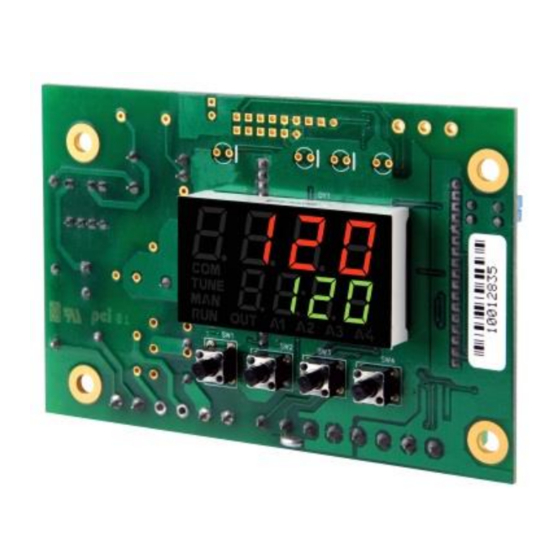
The controller front panel is shown in Fig. 1.
Fig. 1 – Front panel elements
Display: Shows the value and status of the controller parameters.
COM indicator: Flashes to indicate communication activity in the
RS485 interface.
TUNE indicator: Stays ON while the controller is in tuning process.
MAN indicator: Signals that the controller is in the manual control
mode.
RUN indicator: Indicates that the controller is active, with the control
output and alarms enabled.
OUT indicator: For relay or pulse control output; it reflects the actual
state of the output. If an analog output is assigned for control, the
OUT indicator lights continuously.
A1, A2, A3 and A4 indicators: signalize the occurrence of alarm
situation.
P Key (Program key):
used to walk through the menu
P
parameters.
Back Key: used to retrocede parameters.
B
Increment key and
- Decrement key: allow altering the
values of the parameters.
When the controller is turned on, its firmware version is delayed for 3
seconds, after which the controller starts normal operation. The
values of PV and SP are displayed and the outputs are enabled.
In order to operate appropriately, the controller needs a configuration
that is the definition of each one of the several parameters presented by
the controller. The user must be aware of the importance of each
parameter and for each one determine a valid condition or a valid value.
Important:
Always the first parameter to set is the input type.
The parameters are grouped in levels according to their functionality
and operation easiness. The 7 levels of parameters are:
LEVEL
1 - Operation
2 - Tuning
3- R&S Programs
4- Alarms
5- Scale
6- Outputs
7- Calibration
Table 1 – Cycles of Parameters
ACCESS
Free access
Reserved access
Advertisement
Table of Contents

Related Manuals for Novus N120


Summary of Contents for Novus N120
- Page 1 INSTRUCTIONS MANUAL – V2.0x B INTRODUCTION N120 has all the main features needed for control and alarm functions in different industrial processes. It accepts in a single model the majority of the sensors and signals used in the industry and provides the main output types required for dual action control (Heat and Cool) and alarm monitoring.
-
Page 2: Configuration / Features
Control 1 output (TR1 This alarm is activated by the Ramp & Soak program (refer to the Control 2 output (TR2 programs of ramp and soak section on how to set the event alarm). Table 3 – Outputs Functions NOVUS AUTOMATION 2/14... -
Page 3: Control Mode
CONTROL 2 various combinations of times t1 and t2. The timer functions can be The N120 offers a second independent control output (Control Output configured in parameters A1t1, A1t2, A2t1, A2t2, A3t1, A3t2, 2). This output, with only proportional action is generally used in A4t1 and A4t2. -
Page 4: Usb Interface
MANUAL while forcing MV to assume the user configured value in the 1E.ov parameter. This function requires that one of the alarms be configured as 1Err and the 1E.ov parameter (control output percentage) programmed with a value other then 0 (zero). NOVUS AUTOMATION 4/14... -
Page 5: Description Of The Parameters
Pr. t b parameter. Enables control outputs and alarms. YES - Outputs enables. - Outputs not enabled. Fig. 3a – Input, outputs, mains supply and RS485 interface. NOVUS AUTOMATION 5/14... -
Page 6: Tuning Level
Cycle Time. PWM period in seconds. Can only be viewed - Inhibits this blocking function. bla4 if proportional band is other than zero. Histeresis of Alarm. Defines the difference between the xya1 value of PV at which the alarm is triggered and the value NOVUS AUTOMATION 6/14... -
Page 7: Calibration Cycle
Calibration levels are protected. Operation (except SP), Tunning, R&S Program, Alarm, Scale, Outputs and Calibration levels are protected. Operation, Tunning, R&S Program, Alarm, Scale, Outputs and Calibration levels are protected. Table 7 – Levels of Protection for the Configuration NOVUS AUTOMATION 7/14... -
Page 8: Programs Of Ramp And Soak
Only PID parameters (Control Output 1) can be automatically calculated by N120. Control Output 2 Proportional Band and Overlap must be manually adjusted. Automatic tuning: In the beginning of the automatic tuning the Fig. -
Page 9: Specifications
The oscillations themselves imposed by the NOVUS AUTOMATION 9/14... -
Page 10: Maintenance
Note: When checking the controller calibration with a Pt100 simulator, pay attention to the simulator minimum excitation current requirement, which may not be compatible with the 0.170 mA excitation current provided by the N120. CALIBRATION OF THE ANALOGICAL OUTPUT ... -
Page 11: Appendix 1 - Software Logchart-Ii
Alarm: the acquisition starts whenever the condition associated with the alarm 1 (AL1) controller is met. Otherwise, stops the acquisition. Fig. 2 – Selection of USB serial port where the N120 controller is connected. End of the acquisitions: The options for the ending of acquisitions are: Once a valid serial port is selected, the icons for communication with the ... -
Page 12: Collecting The Data
Fig. 6 - Graphical display of the collected data After opening the "Device Manager" you can check which port Serial (COM) associated with the N120. As can be identified in Fig. 9a and The collecting does not stop the acquisition process of measurement Fig.9b, the N120 is associated with COM7. -
Page 13: Important Recommendation
SELECTION If necessary modify the Serial Port (COM) associated with the N120 select the "USB Serial Port (COM X)" where is connected the N120. Go to "Action / Properties" and in the "Port Settings" then click "Advanced ..." tab, as Fig. 10a and Fig. 10b. If this tab does not appear, the driver was not installed properly and you should reinstall the software DigiConfig. -
Page 14: Communication Protocol
Follows a description of the usual communication registers. For full documentation download Registers Table Serial Communication in the N120 section of our web site. Address Parameter Register Description 0000 Active SP Read: Active control SP (main SP, from ramp and soak or from remote SP).
Need help?
Do you have a question about the N120 and is the answer not in the manual?
Questions and answers