Table of Contents
Advertisement
Quick Links
Controller N2000
UNIVERSAL PROCESS CONTROLLER – INSTRUCTIONS MANUAL – V2.1x C
PRESENTATION
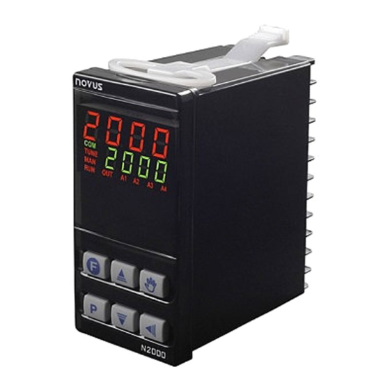
The N2000 is a process controller incorporating a PID algorithm and
universal inputs (sensor and standard signals) and outputs (logical,
relay and analog outputs). It holds in one single instrument all de main
features that are needed for the vast majority of industrial processes.
SAFETY SUMMARY
The symbols below are used on the equipment and throughout this
document to draw the user's attention to important operational and
safety information.
CAUTION or WARNING:
Read complete instructions prior to
installation and operation of the unit.
All safety related instructions that appear in the manual must be
observed to ensure personal safety and to prevent damage to either
the instrument or the system. If the instrument is used in a manner
not specified by the manufacturer, the protection provided by the
equipment may be impaired.
OVER-TEMPERATURE PROTECTION
When designing any control system it is essential to consider what
will happen if any part of the system should fail. In temperature
control applications the primary danger is one in which the heating
remains constantly on. In any application where physical injury or
destruction of equipment might occur, it is recommend to install an
independent protection equipment, with a separate temperature
sensor, to disable the heating circuit in case of overheating. Please
note that the alarm relays within the controller will not give protection
under all failure conditions.
NOVUS AUTOMATION
CAUTION or WARNING:
Electrical Shock Hazard
INSTALLATION
Insert the unit into the panel cut-out and slide the mounting clamp
from the rear to a firm grip at the panel.
RECOMMENDATIONS FOR INSTALLATION
•
Input signal wires should be laid out away from power lines and
preferably inside grounded conduits.
•
Instrument mains (line) supply should be suitable for this purpose
and should not be shared.
•
In controlling and monitoring applications, possible consequences
of any system failure must be considered in advance. The internal alarm
relay does not warrant total protection.
•
Use of RC filters (47 R and 100 nF, serial) are highly recommended
when driving solenoids, contactor coils or other inductive loads.
Figure 1 - Backpannel terminals
ELECTRICAL CONNECTIONS
All electrical connections are made to the screw terminals at the rear
of the controller. They accept wire sizes from 0.5 to 1.5 mm2 (16 to
22 AWG). The terminals should be tightened to a torque of 0.4 Nm
(3.5 lb in).
To minimize the pick-up of electrical noise, the low voltage DC
connections and the sensor input wiring should be routed away from
high-current power conductors. If this is impractical, use shielded
cables. In general, keep cable lengths to a minimum.
POWER WIRING
If high voltage is applied to
a low voltage input,
irreversible damage will
occur
Figure 2 – High and Low Voltage AC power wiring
Man 5001132
1/9
Advertisement
Table of Contents

Related Manuals for Novus N2000


Summary of Contents for Novus N2000
- Page 1 Man 5001132 PRESENTATION INSTALLATION The N2000 is a process controller incorporating a PID algorithm and Insert the unit into the panel cut-out and slide the mounting clamp universal inputs (sensor and standard signals) and outputs (logical, from the rear to a firm grip at the panel.
-
Page 2: Operation
CYCLE ACCESS 1- Operation Free access parameters * 2- Tuning 3- R&S Program 4- Alarms Reserved access parameters ** 5- Input Configuration 6- I/Os 7- Calibration Fig. 9 - 4-20 mA transmitter using the N2000 24 Vdc supply NOVUS AUTOMATION... - Page 3 Controller N2000 *These parameters can be viewed but not changed if the cycle is The function code of each I/O can be selected among the options on protected. Table 2. Only valid function codes are displayed for each I/O (for example, I/O1, which is a relay, can be configured with functions 0 to **Requires a key combination to access the cycle.
-
Page 4: Alarms Function
Controller N2000 ALARMS FUNCTION ALARM TIMER FUNCTIONS The controller has 4 independent alarms. They can be programmed Alarms 1 and 2 can be programmed to have timer functions. The 3 to operate with nine different functions, represented in Table 3. -
Page 5: Configuration Parameters
Controller N2000 RAMP AND SOAK PROFILE PROGRAMMING CYCLE key in front panel executes function 6 of Table 2: tbas tbas tbas tbas TIME BASE: Selects the time base for the ramp and soak. Auto/Manual mode change. Operation of this key is enabled in Valid for all profile programs. -
Page 6: Configuration Cycle
Controller N2000 CONFIGURATION CYCLE I I I I o 5 I/O 5 FUNCTION: Selects the I/O function to be used at I/O 5 (Analog Output). Functions 0 to 15 are available (See Table type type type type INPUT TYPE: Selects the input signal type to be connected 2). -
Page 7: Ramp And Soak Profile Program
SOLUTION Proportional Band Slow Response Decrease Large Oscillation Increase Integral Rate Slow Response Incre ase Large Oscillation Decrease Derivative Time Slow Response or Instability Decrease Large Oscillation Increase Table 6 - Suggestions for manual tuning of PID parameters NOVUS AUTOMATION... -
Page 8: Serial Communication
Controller N2000 CALIBRATION SERIAL COMMUNICATION The indicator can be supplied with an asynchronous RS-485 digital INPUT CALIBRATION communication interface for master-slave connection to a host computer (master). All inputs are factory calibrated and recalibration should only be done by qualified personnel. If you are not familiar with these procedures The indicator works as a slave only and all commands are started by do not attempt to calibrate this instrument. -
Page 9: Specifications
Controller N2000 SPECIFICATIONS WARRANTY DIMENSIONS:............48 x 96 x 92 mm (1/16 DIN). This product is covered by a 12-month warranty provided the purchaser Approximate weight: 150 g presents the sales receipt and the following conditions are met: PANEL CUT-OUT:..........45 x 93 mm (+0.5 -0.0 mm) •...
Need help?
Do you have a question about the N2000 and is the answer not in the manual?
Questions and answers