Table of Contents
Advertisement
Quick Links
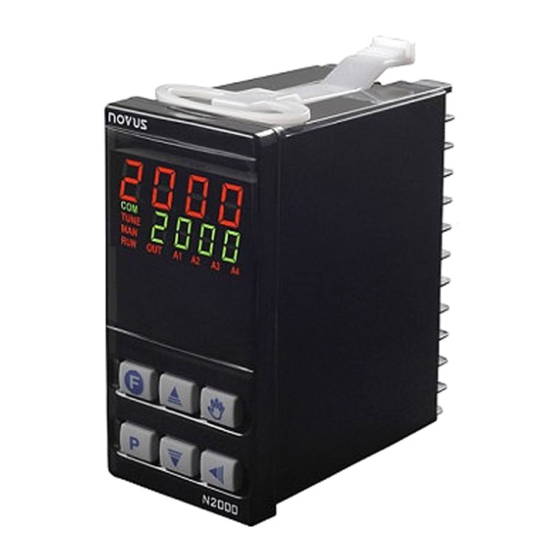
Controller N2000
UNIVERSAL PROCESS CONTROLLER – INSTRUCTIONS MANUAL – V3.0x E
SAFETY ALERTS
The symbols below are used on the equipment and throughout this
document to draw the user's attention to important operational and
safety information.
CAUTION or WARNING:
Read complete instructions prior to
installation and operation of the unit.
All safety related instructions that appear in the manual must be
observed to ensure personal safety and to prevent damage to either
the instrument or the system. If the instrument is used in a manner
not specified by the manufacturer, the protection provided by the
equipment may be impaired.
PRESENTATION
The N2000 is an extraordinarily versatile process controller. It holds
in one single instrument all the main features needed for the vast
majority of industrial processes. It accepts in a single model virtually
all the sensors and signals used in the industry and provides the
main output types required for the operation of diverse processes.
The configuration can be performed directly on the controller or through
the USB interface. The NConfig software (free) is the configuration
management tool. Connected to the USB of a Windows computer, the
controller is recognized as a serial communications port (COM) running
with a Modbus RTU protocol.
Through the USB interface, even if disconnected from the power
supply, the configuration performed in a piece of equipment can be can
be saved in a file and repeated in other pieces of equipment that
require the same configuration.
It is important that the users read carefully this manual before using the
controller. Verify if the release of this manual matches the instrument
version (the firmware version is shown when the controller is
energized).
• Multi-sensor universal input (sensors and standard signals);
• Relay, 4-20 mA and logic pulse control outputs all available in the
standard model;
• Self-tuning of PID parameters;
• Automatic / Manual function with "bumpless" transfer;
• Four modes of independents alarms, with functions of minimum,
maximum, differential (deviation), open sensor and event;
• Timer functions that can be associated to the alarms;
• Retransmission of PV or SP in 0-20 mA or 4-20 mA;
• Input for remote setpoint;
• Digital input with 5 functions;
• Programmable soft-start;
• 7 setpoint profile programs with 7 segments each, with the ability
to be linked together for a total of 49 segments;
• RS-485 Serial communication, MODBUS RTU protocol;
• Password for parameters protection;
• Universal power supply.
NOVUS AUTOMATION
CAUTION or WARNING:
Electrical Shock Hazard
CONFIGURATION
INPUT TYPE SELECTION
Select the input type (in parameter "tYPE") from Table 1 below.
TYPE
CODE
J
Range: -110 a 950 ºC (-166 a 1742 ºF)
Tc j
K
Range: -150 a 1370 ºC (-238 a 2498 ºF)
Tc k
T
Range: -160 a 400 ºC (-256 a 752 ºF)
Tc t
N
Range: -270 a 1300 ºC (-454 a 2372 ºF)
Tc n
R
Range: -50 a 1760 ºC (-58 a 3200 ºF)
Tc r
S
Range: -50 a 1760 ºC (-58 a 3200 ºF)
Tc s
B
Range: 400 a 1800 ºC (752 a 3272 ºF)
Tc b
E
Range: -90 a 730 ºC (-130 a 1346 ºF)
Tc e
Pt100
Range: -200 a 850 ºC (-328 a 1562 ºF)
Pt
0–50 mV
L. 0 . 5 0
4-20 mA
Linear Signals
L. 4 . 2 0
Programmable indication from-1999 to 9999
0-5 Vdc
L0. 5
0-10 Vdc
L0. 1 0
4-20 mA input with Square Root extraction.
4-20 mA
Sqrt
Programmable indication from-1999 to 9999
ln j
Ln k
ln t
ln n
4-20 mA
Non Linear Analog Signals
NO
ln r
Indication range depends on the selected sensor
LINEAR
ln s
ln b
ln E
Ln. P t
Table 1 - Input Types
Note: All input types are factory calibrated.
OUTPUTS, ALARMS AND DIGITAL INPUTS CONFIGURATION
The controller input/output channels can assume multiple functions,
depending on configuration: control output, alarm output, digital
output, digital input, and PV or SV analog retransmission. These
channels are identified as I/O1, I/O2, I/O3, I/O4, I/O 5 and I/O6.
The basic controller model comes loaded with:
I/O1 and I/O2 - SPDT relay output;
I/O3 and I/O4 - SPST relay output;
I/O5 - analog output (0-20 or 4-20 mA), pulse 10 V max, digital I/O;
I/O6 - Digital Input.
Note: When a function is selected to operate through digital
input, the controller does not respond to the equivalent function
command given in the frontal keypad.
CHARACTERISTICS
1/11
Advertisement
Table of Contents

Related Manuals for Novus N2000


Summary of Contents for Novus N2000
- Page 1 Range: -200 a 850 ºC (-328 a 1562 ºF) 0–50 mV L. 0 . 5 0 The N2000 is an extraordinarily versatile process controller. It holds in one single instrument all the main features needed for the vast 4-20 mA Linear Signals L.
-
Page 2: Alarms Functions
Controller N2000 The function to be used in each channel of I/O is defined by the user Note: Even when the execution of the program is interrupted, in accordance with the options shown in the Table 2. the control output remains active and controlling the process at the point (Setpoint) of interruption. -
Page 3: Alarm Initial Blocking
Controller N2000 The alarm functions are described in Table 3. The analog output signal is scaleable, with the output range determined by the values programmed in the parameters “SPLL” TYPE PROMPT ACTION and “SPkL”. To obtain a voltage output, connect a resistor shunt to the current output terminals. -
Page 4: Recommendations For Installation
Controller N2000 USB INTERFACE The USB interface is used for CONFIGURING or MONITORING the controller. The NConfig software must be used for the configuration. It makes it possible to create, view, save and open configurations from the equipment or files in your computer. The tool for saving and... -
Page 5: Operation
Parameter display/SV: shows the SV (Setpoint Variable) value and the value of other parameters of the controller. Fig. 4c - 4-20 mA transmitter using the N2000 24 Vdc supply COM Indicator: Flashes when communication messages are sent by Remote setpoint the controller. -
Page 6: Protection Of Configuration
Controller N2000 Other functions, including alarms, ramp and soak, timer, digital input, Master Password etc., may be useful for a better system performance. The parameters The Master Password is intended for allowing the user to define a are grouped in 7 cycles. - Page 7 Controller N2000 ALARM CYCLE Control Hysteresis: This parameter is only shown for Xyst ON / OFF control. Functions of Alarms. Defines the functions for the Fva1 Hysteresis Displayed only if proportional band = 0. alarms among the options of the Table 3.
-
Page 8: Calibration Cycle
Controller N2000 Defines the upper limit for adjustment of SP. F Key Function: Selects the I/O function assigned to Spxl f. f nc the front panel key. Available functions are: For the linear analog input types available (0-20 mA, Setpoint High... -
Page 9: Ramp And Soak Profile Program
(time priority as opposed to SV priority). resumes at the beginning of the segment it currently is. The ramp and soak event function is used to activate alarms at any segment of program 1. This applies only to program 1. NOVUS AUTOMATION 9/11... -
Page 10: Serial Communication
Controller N2000 AUTO TUNE ANALOG OUTPUT CALIBRATION 1) Select type 11 or 12 at the I/O5 prompt. During auto tune the process is controlled in ON/OFF mode at the 2) Connect a current meter at the analog output. programmed SetPoint (SV). -
Page 11: Specifications
......Thermocouple E, N, R, S and B: 0.25 % of span ±3 ºC ................... Pt100: 0.2 % of span NOVUS warrants to the original purchaser that this product is free from ..........4-20 mA, 0-50 mV, 0-5 Vdc: 0.2 % of span.
Need help?
Do you have a question about the N2000 and is the answer not in the manual?
Questions and answers