Table of Contents
Advertisement
Quick Links
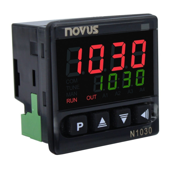
N1030T Controller
TEMPERATURE CONTROLLER AND TIME – INSTRUCTION MANUAL – V2.0x (*)
(*) The V2.0x version also covers V1.05 version controllers, except
for the points indicated in the text.
SAFETY ALERTS
The symbols below are used on the equipment and throughout this
document to draw the user's attention to important operational and
safety information
CAUTION:
Read the manual thoroughly
before installing and operating
the equipment.
All safety related instructions that appear in the manual must be
observed to ensure personal safety and to prevent damage to either
the instrument or the system. If the instrument is used in a manner not
specified by the manufacturer, the protection provided by the
equipment may be impaired.
INSTALLATION / CONNECTIONS
The controller should be fixed to a panel, following the sequence of
steps below:
•
Make a cutout in the panel according to the Specifications.
•
Remove the controller fixing clip.
•
Insert the controller into the cutout from the front of the panel.
•
Replace the clip on the controller, pressing until it is well fixed.
INSTALLATION RECOMMENDATIONS
•
Input signal conductors should run through the plant separately
from output and supply conductors. If possible, in grounded
conduits.
•
The power supply for electronic instruments must come from a
network dedicated to the instrumentation.
•
The use of RC FILTERS (noise suppressors) in contactor coils,
solenoids, etc. is recommended.
•
In control applications, it is essential to consider what can
happen when any part of the system fails. The controller internal
devices do not provide full protection.
ELECTRICAL CONNECTIONS
The figure below shows the connections on the back panel of the
controller:
Figure 1 –
Connections of the back panel
NOVUS AUTOMATION
CAUTION OR DANGER:
Electrical shock hazard.
FEATURES
INPUT TYPE DEFINITION
The temperature sensor or input type to be used by the controller is
defined during equipment configuration. Table 01 shows the
available options:
TYPE
CODE
Thermocouple J
Tc j
Range: -110.0 to 950.0 °C (-166.0 to 1742 °F)
Thermocouple K
Range: -150.0 to 1370 °C (-238.0 to 2498 °F)
Tc k
Thermocouple T
Tc t
Range: -160.0 to 400.0 °C (-256.0 to 752.0 °F)
Pt100
Range: -200.0 to 850.0 °C (-328.0 to 1562 °F)
Pt
Table 1 – Input types
The input type should be the first parameter to be configured. Any
modifications on the input type will automatically change other
related parameters. When changing the sensor type, you should
check the overall condition of the configuration.
OUTPUTS
The controller has two outputs, OUT1 and OUT2, which have the
following characteristics:
OUTPUT OUT1 - Logical pulse, 5 Vdc / 25 mA or
Output Relay SPST-NA / 1.5 A / 240 Vac
OUTPUT OUT2 - Output Relay SPST-NA / 1.5 A / 240 Vac
These outputs can be configured to operate as Control Output,
Alarm Output, or Output Timers T1 or T2.
CONTROL OUTPUT ((TRL)
The process control output can operate in ON/OFF mode or in PID
mode.
To operate in ON/OFF mode, the value set in parameter PB must be
0.0.
With values other than zero in parameter PB, the controller operates
in PID mode. The values for the PID parameters can be set
automatically with the help of Auto Tune (ATvN).
ALARM OUTPUT (A1)
The controller has an alarm that can be directed to any of the outputs.
When enabled, you can configure the alarm to operate with one of the
functions described in Table 02:
off
Alarm off.
Alarm of absolute minimum
value. It triggers when the
lo
value of measured PV is
below the value defined for
alarm Setpoint (SPA1).
Alarm of absolute maximum
value. It triggers when the
ki
value of measured PV is
above the value defined for
alarm Setpoint (SPA1).
MEASUREMENT RANGE
PV
SPA1
PV
SPA1
1/7
Advertisement
Table of Contents

Related Manuals for Novus N1030T


Summary of Contents for Novus N1030T
- Page 1 N1030T Controller TEMPERATURE CONTROLLER AND TIME – INSTRUCTION MANUAL – V2.0x (*) (*) The V2.0x version also covers V1.05 version controllers, except FEATURES for the points indicated in the text. INPUT TYPE DEFINITION SAFETY ALERTS The temperature sensor or input type to be used by the controller is The symbols below are used on the equipment and throughout this defined during equipment configuration.
- Page 2 N1030T Controller TIMERS Differential alarm. In this function, SPA1 represents an error (difference) between CONTROL PV and SP. The controller has two timers, T1 and T2, which have different modes of operation. Timing starts with T1 and, at the end of T1, starts with SP + SPA1 SP –...
- Page 3 N1030T Controller OPERATION PARAMETERS DESCRIPTION The front panel of the controller can be seen in the figure below: OPERATION CYCLE PV Indication Screen. The upper (red) display shows the measured temperature value (PV). The lower display (green) shows the control Setpoint value (SP), which is the desired value for the process temperature.
- Page 4 N1030T Controller kyst offs Control hysteresis. Hysteresis value in degrees for Offset. Parameter that allows you to make corrections to ON/OFF control. the indicated PV value. Adjustable between 0 and the measurement range Spll SP Low/High Limit. Sets the lower/upper limits for width of the selected input type.
- Page 5 N1030T Controller During automatic tuning, the TUNE indicator remains lit on the front Disabled control. of the controller. You must wait until the tuning is finished before you Enable/disable command via key (****). can use the controller. Parameter shown in this cycle when set in parameter During the execution of the automatic tuning, it is possible to induce r.en...
- Page 6 N1030T Controller MAINTENANCE PARAMETER PARAMETER DESCRIPTION FACTORY PROBLEMS WITH THE CONTROLLER T2 time interval setting. 0:20 Wiring errors and improper programming represent most of the problems that can occur when using the controller. A final review can Control output behavior after T1 + T.e.(.o...
- Page 7 N1030T Controller SPECIFICATIONS DIMENSION: .............. 48 x 48 x 35 mm Approximate weight: ............... 60 g POWER SUPPLY: Standard Model ......100 to 240 Vac (±10 %), 50/60 Hz ..........48 to 240 Vdc (±10 %) 24 V Model:....... 12 to 24 Vdc / 24 Vac (-10 % / +20 %) Maximum Consumption: ............
Need help?
Do you have a question about the N1030T and is the answer not in the manual?
Questions and answers