Table of Contents
Advertisement
Quick Links
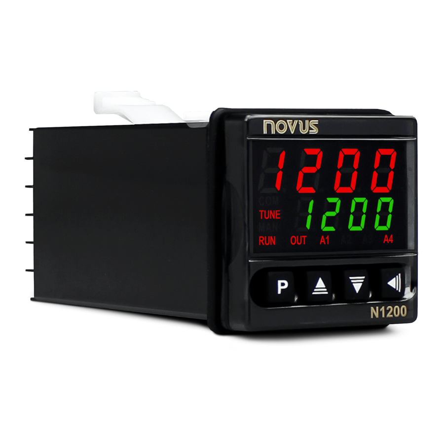
Controller N1200
UNIVERSAL CONTROLLER - INSTRUCTIONS MANUAL – V2.0x C
SAFETY ALERTS
The symbols below are used on the equipment and throughout this
document to draw the user's attention to important operational and
safety information.
CAUTION:
Read the manual thoroughly
before installing and operating the
equipment.
All safety related instructions that appear in the manual must be
observed to ensure personal safety and to prevent damage to either
the instrument or the system. If the instrument is used in a manner
not specified by the manufacturer, the protection provided by the
equipment may be impaired.
INTRODUCTION
The N1200 is an extraordinarily versatile process controller. It holds
in one single instrument all the main features needed for the vast
majority of industrial processes. It accepts in a single model virtually
all the sensors and signals used in the industry and provides the
main output types required for the operation of diverse processes.
The configuration can be performed directly on the controller or
through the USB interface. The NConfig software (free) is the
configuration management tool. Connected to the USB of a Windows
computer, the controller is recognized as a serial communications
port (COM) running with a Modbus RTU protocol.
Through the USB interface, even if disconnected from the power
supply, the configuration performed in a piece of equipment can be
can be saved in a file and repeated in other pieces of equipment that
require the same configuration.
It is important that the users read carefully this manual before using
the controller. Verify if the release of this manual matches the
instrument version (the firmware version is shown when the controller
is energized). The N1200 main characteristics are:
Multi-sensor universal input;
Protection for open sensor in any condition;
Relay, 4-20 mA and logic pulse control outputs all available in
the standard model;
Self-tuning of PID parameters;
Automatic / Manual function with "bumpless" transfer;
Four modes of independents alarms, with functions of minimum,
maximum, differential (deviation), open sensor and event;
Timer functions that can be associated to the alarms;
Retransmission of PV or SP in 0-20 mA or 4-20 mA;
Input for remote setpoint;
Digital input with 5 functions;
Programmable soft-start;
20 setpoint profile programs with 9 segments each, with the
ability to be linked together for a total of 180 segments;
Password for parameters protection;
Universal power supply.
NOVUS AUTOMATION
CAUTION OR DANGER:
Electrical Shock Hazard
CONFIGURATION / FEATURES
INPUT TYPE SELECTION
Select the input type (in parameter "tYPE") from Table 1 below.
TYPE
CODE
J
Range: -110 to 950 ºC (-166 to 1742 ºF)
Tc j
K
Range: -150 to 1370 ºC (-238 to 2498 ºF)
Tc k
T
Range: -160 to 400 ºC (-256 to 752 ºF)
Tc t
N
Range: -270 to 1300 ºC (-454 to 2372 ºF)
Tc n
R
Range: -50 to 1760 ºC (-58 to 3200 ºF)
Tc r
S
Range: -50 to 1760 ºC (-58 to 3200 ºF)
Tc s
B
Range: 400 to 1800 ºC (752 to 3272 ºF)
Tc b
E
Range: -90 to 730 ºC (-130 to 1346 ºF)
Tc e
Pt100
Range: -200 to 850 ºC (-328 to 1562 ºF)
Pt
0-20 mA
L0. 2 0
4-20 mA
L4. 2 0
0–50 mV
L0. 5 0
Programmable indication from -1999 to 9999.
0-5 Vdc
L0. 5
0-10 Vdc
L0. 1 0
ln j
Ln k
ln t
4-20 mA
ln n
NON
ln r
Indication range depends on the selected sensor
LINEAR
ln s
ln b
ln E
Ln. P t
Table 1 - Input types
Note: All input types are factory calibrated.
CONFIGURATION OF OUTPUTS, ALARMS AND DIGITAL INPUTS
The controller input and output channels (I / O) can assume multiple
functions: control output, digital input, digital output, alarm output,
retransmission of PV and SP. These channels are identified as I / O
1, I / O 2, I / O 3, I / O 4 and I / O 5.
The basic controller model comes loaded with the following features:
I / O 1- output to Relay SPST-NA;
I / O 2- output to Relay SPST-NA;
I / O 5- current output, digital output, digital input;
Optionally, other features can be added, as shown under the item
"Identification" in this manual:
- 3R:
I / O3 with output to SPDT relay;
- DIO: I / O3 and I / O4 as digital input and output channels;
- HBD: Heater break detect;
- 485:
Serial Communication;
The function to be used in each channel of I/O is defined by the user
in accordance with the options shown in the Table 2.
RANGE OF MEASUREMENT
Linear Signals
Non Linear Analog Signals
1 / 13
Advertisement
Table of Contents

Related Manuals for Novus N1200


Summary of Contents for Novus N1200
- Page 1 0-10 Vdc INTRODUCTION L0. 1 0 ln j The N1200 is an extraordinarily versatile process controller. It holds Ln k in one single instrument all the main features needed for the vast ln t majority of industrial processes. It accepts in a single model virtually...
-
Page 2: Configuration Of Alarms
Controller N1200 Note: Even when the execution of the program is interrupted, the FUNCTION OF I/O CODE TYPE OF I/O control output remains active and controlling the process at the point Without Function Output (Setpoint) of interruption. The program will resume its normal execution... - Page 3 Controller N1200 Using the Alarm 1 as example. INITIAL BLOCKING OF ALARM The initial blocking option inhibits the alarm from being recognized if difk – Alarm of Maximum Differential Value an alarm condition is present when the controller is first energized (or Triggers when the value of PV is above the defined point by: after a transition from run YES NO).
-
Page 4: Electrical Connections
Controller N1200 The determination of the PID parameters (Pb, Ir and Dt) is described The USB interface IS NOT SEPARATE from the in the item DETERMINATION OF PID PARAMETERS of this manual. signal input (PV) or the controller’s/indicator’s digital inputs and outputs. It is intended for temporary use... -
Page 5: Operation
Controller N1200 Power Supply Connections Digital Input Connections Figures 5a and 5b show switches driving I/O 3 and I/O 5. The same scheme applies to I/O 4 Observe the power requirement for the unit. of required power supply Figure 2 – Power supply connections Input Connections Figure 5a –... -
Page 6: Cycle Of Tuning
Controller N1200 In order to operate appropriately, the controller needs a configuration Screen for indication only. When a ramp and soak p. s eg that is the definition of each one of the several parameters presented program is active, this parameter shows the number by the controller. -
Page 7: Alarm Hysteresis
Controller N1200 triggered and the value at which it is turned off (in xya2 Upper limit for the control output - Maximum ovkl engineering units). percentage for the control output when in xya3 Output High automatic mode and in PID. Typically configured... -
Page 8: Calibration Cycle
Controller N1200 REMOTE SETPOINT HIGH LIMIT: defines the full Function of the channel I/O 5: Selection of the rskl Io 5 function used in the channel I/O 5, according to the scale indication of the Remote Setpoint Remote SP Table 2. -
Page 9: Protection Of Configuration
The protection system built into the controller blocks for 10 minutes T4=0 Time the access to protected parameters after 5 consecutive frustrated Figure 9 - Program example with few segments attempts of guessing the correct password. NOVUS AUTOMATION 9 / 13... -
Page 10: Link Of Programs
Controller N1200 The program tolerance defines the maximum deviation between PV and SP for the execution of the profile. If this deviation is exceeded, the program will be halted until the deviation falls to within the tolerance band. Programming 0 (zero) in the “Ptol” parameter disables the program tolerance and the profile execution will continue regardless of the PV value (time priority as opposed to SP priority). -
Page 11: Maintenance
Controller N1200 The methods of automatic tuning and auto-adaptative tuning are ANALOG OUTPUT CALIBRATION appropriate for most of the industrial processes. However, there may Configure I/O 5 for the current output to be calibrated, be it be processes or even specific situations where the methods are not control or retransmission. -
Page 12: Specifications
Table Serial Precision: . Thermocouples J, K, T, E: 0.25 % of the span 1 ºC Communication in the N1200 section of our web site – ....Thermocouples N, R, S, B: 0.25 % of the span 3 ºC www.novusautomation.com. -
Page 13: Warranty
Controller N1200 IDENTIFICATION N1200 - 3R - 485 - A: Controller Model: N1200; B: Optional I/Os: Blank (basic version, without I/O3 nor I/O4); (SPDT Relay in I/O3); (Digital I/Os in I/O3 and I/O4); (Burnt-Out Resistance detection); C: Digital Communication: Blank (basic version, without serial communication);...
Need help?
Do you have a question about the N1200 and is the answer not in the manual?
Questions and answers