Table of Contents
Advertisement
Quick Links
N2000S Controller
UNIVERSAL PROCESS CONTROLLER
USER GUIDE – V3.0x
SAFETY SUMMARY
The symbols below are used on the equipment and throughout this
document to draw the user's attention to important operational and
safety information.
CAUTION OR WARNING:
Read complete instructions prior to
installation and operation of the
unit.
All safety related instructions that appear in the manual must be
observed to ensure personal safety and to prevent damage to either
the instrument or the system. If the instrument is used in a manner
not specified by the manufacturer, the protection provided by the
equipment may be impaired.
INTRODUCTION
N2000S is a controller for servo positioners with two control relays:
one to open and other to close the valve (or damper). Moreover, it
has an analog output that can be programmed to control or
retransmit input or setpoint signals. Its universal input accepts most
industry manufactured sensors and signals.
Configuration can be entirely achieved through the keyboard. No
circuit changes are required. Selection of input and output type,
alarms configuration, and other especial functions are accessed and
programmed through the frontal panel.
It is important that you read the manual thoroughly before using the
controller. Be sure the manual corresponds to your instrument (the
number of the software version can be seen when the controller is
turned on).
• Sensors break protection in any condition.
• Universal input for multiple sensors without changing hardware.
• Potentiometer input for current position reading.
• Auto-tuning of PID parameters.
• Relay control outputs.
• Automatic/Manual "bumpless" transfer.
• 2 alarm outputs with the following functions: minimum, maximum,
differential (deviation), open sensor and event.
• 2 alarm timers.
• 4-20 mA or 0-20 mA analog output for Process Variable (PV) or
Setpoint (SP) retransmission.
• 4 function digital input.
• Ramp and soak with 7 concatenable 7-segment programs.
• RS-485 serial communication; RTU MODBUS protocol.
• Configuration protection.
• Dual voltage.
NOVUS AUTOMATION
CAUTION OR WARNING:
Electrical Shock Hazard
PRESENTATION / OPERATION
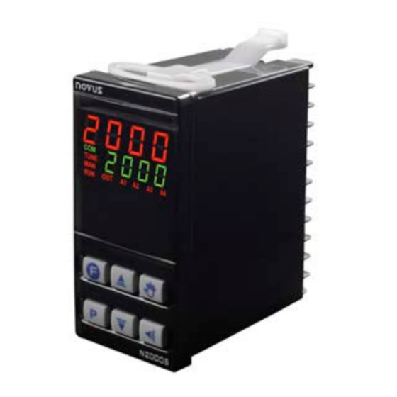
The controller frontal panel is shown in Figure 1:
Figure 1 – Identification of the frontal panel parts
PV / Programming Display: Shows the PV (Process Variable)
value. When in operating or programming mode, shows the
parameter mnemonic.
SP / Parameters Display: Shows the SP (Setpoint) and other
programmable parameter values of the controller.
COM Indicator: Flashes when data is exchanged with the external
environment.
TUNE Indicator: Lights when the controller runs the automatic
tuning operation.
MAN Indicator: Indicates that the controller is in the manual control
mode.
RUN Indicator: Indicates that the controller is active and with control
and alarm outputs enabled.
OUT Indicator: When the analog output (0-20 mA or 4-20 mA) is
configured for control mode, it remains constantly on.
A1, A2 Indicators: Indicates the respective alarm status.
A3 Indicators: Indicates the valve (I/O3) opening output status.
A4 Indicators: Indicates the valve/dumper (I/O4) closing output status.
PROG key: Key used to show the controller programmable
parameters.
BACK Key: Keu used to return to the previous parameter
shown in the parameter display.
Increase and
Decrease keys: Key used to change the
parameter values.
Auto/Man key: Special function key used to switch the control
mode between Automatic and Manual.
Programmable Function Key: Key used to perform the
special functions described in the
When the controller is turned on, its firmware version is displayed for
3 seconds. After that, the controller starts operating normally. The PV
and SV values are displayed in the upper and lower displays,
respectively. Outputs are enabled at this moment as well.
The relay associated to the valve closing is activated during the time
required for the complete valve to close (see parameter Ser. t ) so
that the controller starts operating with a known reference.
Key Functions.
1/9
Advertisement
Table of Contents

Related Manuals for Novus N2000S


Summary of Contents for Novus N2000S
- Page 1 SP / Parameters Display: Shows the SP (Setpoint) and other programmable parameter values of the controller. N2000S is a controller for servo positioners with two control relays: COM Indicator: Flashes when data is exchanged with the external one to open and other to close the valve (or damper). Moreover, it environment.
-
Page 2: Configuration Protection
Controller N2000S CONFIGURATION / RESOURCES To run smoothly, the controller requires some basic configuration: • Input type (Thermocouples, Pt100, 4-20 mA, etc.). INPUT TYPE SELECTION • Control setpoint value (SP). The input type must be selected by the user in the Type parameter •... -
Page 3: Alarm Configuration
Controller N2000S Open = Automatic control. POTENTIOMETER INPUT 7 – Defines the channel to act as Digital Input that turns the The potentiometer of valve position can be seen in the controller. It control on and off (RvN: YES / no). -
Page 4: Alarm Timer
Controller N2000S 9 – Defines the channel to control the programs operation. Minimum Differential • Closed = Enables the program execution. It is activated when the measured value is below the value defined in. Open = Interrupts the program. (SP – Deviation) -
Page 5: Power Supply Connections
Controller N2000S POWER SUPPLY CONNECTIONS MANIPULATED VARIABLE VALUE (MV) (control output): PV Indication (Red) The upper display shows PV value, and the lower display MV Indication shows the percentage of MV applied to the control output. (Green) When in manual control, the MV value can be changed. - Page 6 Controller N2000S PROGRAM TOLERANCE: Maximum deviation between PV vnI t TEMPERATURE: Selects the temperature unit: Celsius (°C) Ptol and SP. Whenever this deviation is exceeded the time or Fahrenheit (°F). Invalid for inputs 16, 17, 18 and 19. unit Program counter is halted until deviation lowers to acceptable values.
-
Page 7: Event Alarm
Controller N2000S EVENT ALARM Ovll OUTPUT OFFSET CALIBRATION: Value to calibrate the This function makes possible to program the activation of alarms in output Low offset of the current control output. specific segments of a program. Calibration For such, alarms must have their function set as rS and be... -
Page 8: Serial Communication
Controller N2000S CALIBRATION FEATURES Signals compliant to the RS-485 standard. Two-wire connection between the master and up to 31 instruments in bus topology (it may INPUT CALIBRATION address up to 247 instruments). Maximum cable length: 1,000 All input and output types are factory calibrated. Recalibration is not meters. -
Page 9: Warranty
Controller N2000S INPUT: T/C, Pt100, voltage and current, configurable according to Table 1 Internal resolution: ............. 19500 levels Display resolution: ....12000 levels (from -1999 to 9999) Input sample rate: ............5 per second Accuracy: ..Thermocouples J, K and T: 0.25 % of span ±1 ºC .......
Need help?
Do you have a question about the N2000S and is the answer not in the manual?
Questions and answers