Table of Contents
Advertisement
Quick Links
Advertisement
Chapters
Table of Contents

Related Manuals for Omron F3SG-*RR Series


Summary of Contents for Omron F3SG-*RR Series
- Page 1 Safety Light Curtain □ F3SG- RR Series http://www.ia.omron.com/f3sg-r Quick Installation Manual Document Title Cat. No. Safty Light Curtain F3SG-RR Series User's Manual Z383-E1 © OMRON Corporation 2017 All Rights Reserved. 9308038-0B Original instructions...
-
Page 2: Table Of Contents
Thank you for purchasing the F3SG-RR Series Safety Light Curtain (hereinafter referred to as the "F3SG- RR"). This document contains simple instructions to install the F3SG-RR. Please download the F3SG-RR User's Manual for full contents of the instructions from our website at: http://www.ia.omron.com/f3sg-r Table of Contents 1. What is Included..........................1 2. -
Page 3: System Components
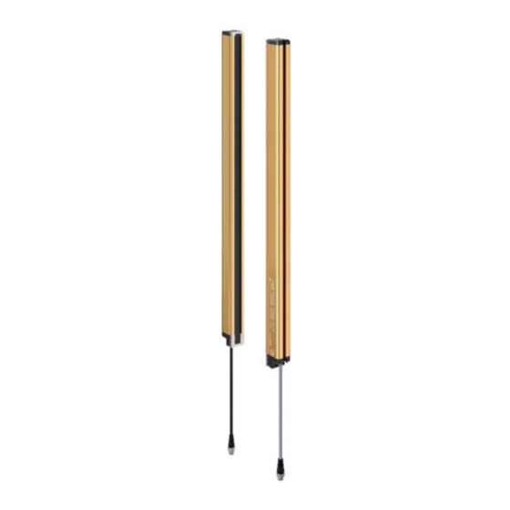
2. System Components <Emitter> <Receiver> Beam center-line mark End cap 1. Top-beam-state indicator (Blue) Beam End cap Emitter 2. PNP/NPN mode indicator (Green) Receiver Rotary Switch Indicator 3. Response time indicator (Green) 4. Sequence error indicator (Yellow) Functional 5. Blanking indicator (Green) earth terminal 6. -
Page 4: Setting With Rotary Switch/End Cap
Setting Wiring Mounting/Beam Alignment Operation check 4. Setting with Rotary Switch/End Cap 4-1. Selecting Function with Rotary Switch F3SG-RR series has the Rotary Switches to configure functions near the power cable. Configure functions with the Rotary Switches before installing F3SG-RR in your site. Make sure to turn the power of the F3SG- RR on after the setting with the Rotary Switches is complete. -
Page 5: Wiring Examples
Setting Wiring Mounting/Beam Alignment Operation check 5.Wiring Examples For input/output circuit and other examples than below, refer to Safety Light Curtain F3SG-RR Series User's Manual. 5-1. EDM enabled, Auto Reset Mode, External Test in 24 V Active (not used), Muting disabled and PNP Outputs [Settings] Function EDM Enabled (factory default setting) *1... -
Page 6: Edm Enabled, Auto Reset Mode, External Test In 0 V Active (Not Used), Muting Disabled And Npn Outputs
Setting Wiring Mounting/Beam Alignment Operation check 5-3. EDM enabled, Auto Reset Mode, External Test in 0 V Active (not used), Muting disabled and NPN Outputs [Settings] Function EDM Enabled (factory default setting) *1 □□ □□ Receiver Auto Reset (factory default setting) *1 F39-JD A-L *6 F39-JD... -
Page 7: Mounting And Beam Alignment
Setting Wiring Mounting/Beam Alignment Operation check 6. Mounting and Beam Alignment 6-1. Mounting with Free-Location Brackets (F39-LGRA) Step1 ■ Dimensions (Check position) Check position [Backside mounting] 46.35 31.4 Step2 Mount Free-Location Bracket (F39-LGRA) 2-M5 or M6 2-M4 Free-Location Bracket (F39-LGRA) 26.3 3.95 2-M5 or M6... - Page 8 Setting Wiring Mounting/Beam Alignment Operation check ■ Mounting 1. Secure the brackets to the wall. <Backside mounting> <Side mounting> Step1 Check position Step2 Mount M5/M6 M5/M6 Screws to mount the brackets to the wall are not included. 2. Loosen the Mounting Screws. Then fit the F3SG-RR housing to the brackets. Mounting Screw (hexagon socket head cap screw (M4×22))
-
Page 9: Mounting With Top/Bottom Brackets (F39-Lgrtb)
Setting Wiring Mounting/Beam Alignment Operation check 6-2. Mounting with Top/Bottom Brackets (F39-LGRTB) ■ Dimensions (Check position) [Backside mounting] Step1 31.4 Check φ9 position 2-M8 4-M5 Step2 Top/Bottom Bracket (F39-LGRTB) Mount Backside:2-M4 Step3 Intermediate Bracket (F39-LGRA) Align 26.3 2-M5 or M6 2-M5 or M6 beams 3.95... -
Page 10: Mounting With Top/Bottom Brackets (F39-Lgrtb-2)
Setting Wiring Mounting/Beam Alignment Operation check 6-3. Mounting with Top/Bottom Brackets (F39-LGRTB-2) ■ Dimensions (Check position) [Backside mounting] Step1 Φ9 Check 2-M8 position 4-M5 2-M6 Step2 Top/Bottom Bracket (F39-LGRTB-2) Mount Backside:2-M4 31.4 Step3 Intermediate Bracket (F39-LGRA) Align beams 26.3 2-M5 or M6 2-M5 or M6 3.95 2-M4... -
Page 11: Mounting With Top/Bottom Brackets (F39-Lgrtb-3)
Setting Wiring Mounting/Beam Alignment Operation check 6-4. Mounting with Top/Bottom Brackets (F39-LGRTB-3) ■ Dimensions (Check position) [Backside mounting] Step1 Check 26.5 position 23.2 2-M8 2-M5 or M6 Step2 Top/Bottom Bracket Mount (F39-LGRTB-3) Backside:2-M4 Step3 31.4 Intermediate Bracket Align (F39-LGRA) beams 26.3 2-M5 or M6 2-M5 or M6... - Page 12 Setting Wiring Mounting/Beam Alignment Operation check ■ Mounting and Beam Alignment 1. Loosen the Alignment Screws and adjust the angle. Then loosen the Mounting Screws of Top/Bottom Bracket (2). <Backside mounting> <Side mounting> Step1 Alignment Screws Alignment Screws Mounting Screws Check (hexagon socket (hexagon socket...
- Page 13 Setting Wiring Mounting/Beam Alignment Operation check 5. (For Intermediate Bracket) Securely tighten the Mounting Screw. Tightening torque: 3.0 N•m (recom- mended) Then loosen the Alignment Screw. Step1 Check position Mounting Screw Alignment Screw Step2 (hexagon socket head Mount cap screw (M4×22)) Mounting Screw Step3 Align...
-
Page 14: Operation Check
Omron Companies shall not be responsible for conformity with any standards, codes or regulations which apply to the combination of the Product in the Buyer’s application or use of the Product. At Buyer’s request, Omron will provide applicable third party certification documents identifying ratings and limitations of use which apply to the Product. This information by itself is not sufficient for a complete determination of the suitability of the Product in combination with the end product, machine, system, or other application or use. - Page 15 F3SG- RR http://www.ia.omron.com/f3sg-r © OMRON Corporation 2017 All Rights Reserved. Original instructions...
-
Page 16: 同梱物のご確認
こ のたびはセー フ テ ィ ラ イ ト カ ーテ ン形 F3SG- □ RR シ リ ーズ ( 以下 F3SG-RR と 呼びます ) を お買い上げ いただ き、 あ り が と う ご ざいます。 本書は F3SG-RR の設置についての簡易説明書です。 F3SG-RR の取扱説明書の全文は下記の当社ウ ェ ブサイ ト よ り ダウン ロー ド し て く だ さ い。 http://www.ia.omron.com/f3sg-r 目次 1. 同梱物のご確認....................................1 2. 各部の名称......................................2 3. -
Page 17: 各部の名称
2. 各部の名称 3. ラ イ ト カ ーテ ン セ ッ ト ア ッ プ手順例 ..3 ページ 設定 ..4 ページ ..6 ページ ..13 ページ * ロー... -
Page 18: ロー タ リ ー Sw ・ 終端キ ャ ッ プ設定
4. ロー タ リ ー SW ・ 終端キ ャ ッ プ設定 4-1. ロー タ リ ー SW での機能切 り 替え 本体の電源ケーブル側に、 機能設定を行 う ためのロー タ リ ー SW があ り ます。 F3SG-RR を設置する前に事 前にロー タ リ ー SW の設定を行っ て く だ さ い。 ロー... -
Page 19: 配線例
5. 配線例 F3SG-RRシ リ ーズユーザーズマニ ュ アル 入出力回路および下記以外の配線例については、 を参照し て く だ さ い。 5-1. EDM 有効、 オー ト リ セ ッ ト モー ド 、 外部テ ス ト 24V ア ク テ ィ ブ ( 機能未使 用時 )、 ミ ュ ーテ ィ ン グ無効、 PNP 出力 [ 各機能の設定... -
Page 20: Edm 有効、 オー ト リ セ ッ ト モー ド 、 外部テス ト 0V ア ク テ ィ ブ ( 機能未使用時 )、 ミ ューテ ィ ング無効、 Npn 出力
EDM 有効、 オー ト リ セ ッ ト モー ド 、 外部テ ス ト 0V ア ク テ ィ ブ 5-3. ( 機能未使用時 )、 ミ ュ ーテ ィ ング無効、 NPN 出力 [ 各機能の設定 ] 機能 外部 リ レーモ ニ タ 有効 (出荷時設定) *1 受光器... -
Page 21: 取 り つけ ・ 光軸調整
6. 取 り つけ ・ 光軸調整 6-1. フ リ ーロ ケーシ ョ ン金具 ( 形 F39-LGRA) を取 り つけ る場合 ■外形寸法図 (取 り つけ位置確認) [ 背面取 り つけ時 ] [ 単位 : mm ] 寸法C 形式中の4桁の数字 (検出幅) 寸法D C-20 形F3SG-4RR□□□□-14 寸法P 形F3SG-4RR□□□□-25 検出幅(C) - Page 22 ■取 り つけ方法 1. 金具を壁面に取 り つけます。 壁面への取 り つけネジは付属 し ていません。 2. 本体固定用ボル ト を緩め、 本体をはめて く だ さ い。 3. 本体固定用ボル ト を固定 し ( 締め付け ト ルク : 3.0N ・ m)、 光軸調整用ボル ト を緩めます。 4. 表示灯を参考に光軸を調整 し 、 光軸調整ボル ト を固定 し ます。 ( 締め付け ト ルク : 3.0N ・ m) フ...
-
Page 23: 上下取付金具 ( 形 F39-Lgrtb) を取 り つける場合
6-2. 上下取付金具 ( 形 F39-LGRTB) を取 り つけ る場合 ■外形寸法図 (取 り つけ位置確認) [ 背面取 り つけ時 ] [ 単位 : mm ] 寸法C 形式中の4桁の数字 (検出幅) 寸法D C-20 寸法G C+27.2+N1+N2 寸法H C+38+N1+N2 寸法I C+58+N1+N2 寸法N1 0~30 寸法N2 0~13 形F3SG-4RR□□□□-14 寸法P 形F3SG-4RR□□□□-25 検出幅(C) 上下取付金具の数... -
Page 24: 上下取付金具 ( 形 F39-Lgrtb-2) を取 り つける場合
6-3. 上下取付金具 ( 形 F39-LGRTB-2) を取 り つける場合 ■外形寸法図 (取 り つけ位置確認) [ 背面取 り つけ時 ] [ 単位 : mm ] 寸法C 形式中の4桁の数字 (検出幅) 寸法D C-20 寸法G C+51+N1+N2 寸法H C+54+N1+N2 寸法I C+88+N1+N2 寸法J C+106+N1+N2 寸法N1 0~30 寸法N2 0~13 形F3SG-4RR□□□□-14 寸法P 形F3SG-4RR□□□□-25 検出幅(C) -
Page 25: 上下取付金具 ( 形 F39-Lgrtb-3) を取 り つける場合
6-4. 上下取付金具 ( 形 F39-LGRTB-3) を取 り つける場合 ■外形寸法図 (取 り つけ位置確認) [ 背面取 り つけ時 ] [ 単位 : mm ] 寸法C 形式中の4桁の数字 (検出幅) 寸法D C-20 寸法G C+39.5+N1+N2 寸法H C+65+N1+N2 寸法I C+84+N1+N2 寸法N1 0~30 寸法N2 0~13 形F3SG-4RR□□□□-14 寸法P 形F3SG-4RR□□□□-25 検出幅(C) 上下取付金具の数... - Page 26 ■取 り つけ方法 と 光軸調整 1. 光軸調整用ボル ト を緩め角度を調整 し 、 上下金具 (2) の本体固定用ボル ト を緩めます。 2. F3SG-RR の筐体 ( 黄色のエ リ ア ) 内に上下金具 (1) の全体が位置する よ う に固定 し て く だ さ い。 ( 推奨締め付け ト ルク : 3.0N ・ m) 3.
- Page 27 5. 本体固定用ボル ト を固定 し ( 締め付け ト ルク : 3.0N ・ m)、 光軸調整用ボル ト を緩めます。 ( 中間取付金具使用時のみ ) 6. 上下取付金具を壁面に固定 し ます。 壁面への取 り つけネジは付属 し ていません。 7. 表示灯を参考に光軸を調整 し 、 光軸調整ボル ト を固定 し ます。 ( 締め付け ト ルク : 3.0N ・ m) 上下取付金具のみの場合、...
-
Page 28: 動作チ ェ ッ ク
●製品に関するお問い合わせ先 お客様相談室 クイック オムロン 0120-919-066 携帯電話 ・ PHS ・ IP電話な ど ではご利用いただけませんので、 下記の電話番号へおかけ く だ さ い。 055-982-5015 電話 (通話料がかかり ます) ■営業時間:8:00∼21:00 ■営業日:365日 ●FAXやWebページでもお問い合わせいただけます。 055-982-5051 / www.fa.omron.co.jp ●その他のお問い合わせ 納期・価格・サンプル・仕様書は貴社のお取引先、または貴社担当オムロン販売員にご相談ください。 オムロン制御機器販売店やオムロン販売拠点は、Webページでご案内しています。 F3SG-RR ク イ ッ ク イ ンス ト ールマニ ュ アル...
Need help?
Do you have a question about the F3SG-*RR Series and is the answer not in the manual?
Questions and answers