Table of Contents
Advertisement
Quick Links
Advertisement
Table of Contents

Related Manuals for Omron F3SG-R Series


Summary of Contents for Omron F3SG-R Series
- Page 1 Safety Light Curtain □ F3SG- RE Series http://www.ia.omron.com/f3sg-r Quick Installation Manual Document Title Cat. No. Safty Light Curtain F3SG-R Series User's Manual Z352-E1 © OMRON Corporation 2015-2016 All Rights Reserved. 8900153-0B Original instructions...
-
Page 2: Table Of Contents
Thank you for purchasing the F3SG-RE Series Safety Light Curtain (hereinafter referred to as the "F3SG- RE"). This document contains simple instructions to install the F3SG-RE. Please download the F3SG-RE User's Manual for full contents of the instructions from our website at: http://www.ia.omron.com/f3sg-r Table of Contents 1. What is Included..........................1 2. -
Page 3: System Components
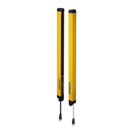
2. System Components <Emitter> <Receiver> Beam center-line mark 1. Top-beam-state indicator (Blue) Beam Emitter Indicator Receiver 2. Operating range indicator (Green) 3. Power indicator (Green) 9. Internal error indicator (Red) 4. Lockout indicator (Red) 10. Lockout indicator (Red) Power Cable 11. -
Page 4: Wiring Examples
Wiring Mounting/Beam Alignment Operation check 4.Wiring Examples For input/output circuit and other examples than below, refer to Safety Light Curtain F3SG-R Series User's Manual. 4-1. Long Mode +24 V Power Supply *1. Refer to F3SG-R Series User's Manual for more information. -
Page 5: Mounting And Beam Alignment
*2. Mounting an emitter or receiver with one bracket is possible for the models of protective height of 0160 to 0270. In this case, locate this bracket at half the Dimension A (or at the center of the sensor length). Refer to Safety Light Curtain F3SG-R Series User's Manual for dimensions of side mounting. F3SG-RE... - Page 6 Wiring Mounting/Beam Alignment Operation check ■ Mounting Note: Although this chapter uses the figures of the F3SG-RA series safety light curtain, the mounting proce- dure of the F3SG-RE series is the same as the F3SG-RA series. Step1 1. Loosen the screw. Check Hexagon socket head Fixed Bracket...
-
Page 7: Mounting With Standard Adjustable Brackets (F39-Lga)
*2. Mounting an emitter or receiver with one bracket is possible for the models of protective height of 0160 to 0270. In this case, locate this bracket at half the Dimension A (or at the center of the sensor length). Refer to Safety Light Curtain F3SG-R Series User's Manual for dimensions of side mounting. F3SG-RE... - Page 8 Wiring Mounting/Beam Alignment Operation check ■ Mounting and Beam Alignment Note: Although this chapter uses the figures of the F3SG-RA series safety light curtain, the mounting proce- dure of the F3SG-RE series is the same as the F3SG-RA series. Step1 1.
- Page 9 Wiring Mounting/Beam Alignment Operation check 5. Perform beam alignment according to the indicators. <Emitter> <Receiver> <Receiver> <Receiver> Step1 TOP(Blue) TOP(Blue) Check position Step2 Mount STB(Green) STB(Green) Step3 BTM(Blue) BTM(Blue) Align beams Angle adjustment range: ±15° 6. Securely tighten the remaining screws. <Backside mounting>...
-
Page 10: Operation Check
Omron Companies shall not be responsible for conformity with any standards, codes or regulations which apply to the combination of the Product in the Buyer’s application or use of the Product. At Buyer’s request, Omron will provide applicable third party certification documents identifying ratings and limitations of use which apply to the Product. This information by itself is not sufficient for a complete determination of the suitability of the Product in combination with the end product, machine, system, or other application or use.
Need help?
Do you have a question about the F3SG-R Series and is the answer not in the manual?
Questions and answers