Table of Contents
Advertisement
Quick Links
Advertisement
Table of Contents

Related Manuals for Omron F3SP-U4P-TGR


Summary of Contents for Omron F3SP-U4P-TGR
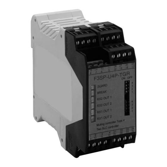
- Page 1 Cat. No. E05-EN-01 F3SP-U4P-TGR Safety Control Unit Safety Level 4 USER´S MANUAL...
- Page 2 F3SP-U4P-TGR User's manual Cat No E05-EN-01 F3SP-U4P-TGR Safety control units, Type 4, For use with 1 or 2 pairs of safety light curtains USER'S MANUAL...
- Page 4 F3SP-U4P-TGR User's manual The device conforms with the EC requirements in compliance with the following standards: -Low Voltage Directive 73/23/EEC -EMC Directive 89/336/EEC -Machinery Directive 98/37/EC -IEC 61496-1: 1997 -IEC 61496-2 ed.2 IEC 2001 (CDV draft 8) -DIN V VDE 0801: 1990 and...
-
Page 5: Table Of Contents
LED DIAGNOSTIC ............... 24 FINAL CHECKS................25 10 ROUTINE MAINTENANCE............25 11 GENERAL INFORMATION AND USEFUL DATA...... 26 11.1 OMRON LIGHT CURTAINS TO BE USED WITH THE F3SP-U4P-TGR ..26 12 TECHNICAL DATA..............27 13 OVERALL DIMENSIONS............. 28... -
Page 6: F3Sp-U4P-Tgr Index
• The control unit does not contain parts subject to maintenance. Do not open the control unit for any reason, and in case of failure, send it to our laboratories, indicating the fault and the operation period. •... -
Page 7: General Information
DIN/OMEGA rail; it has 32 removable screw terminals to which it is possible to connect from 1 to 2 pairs of light curtains. This control unit has the double ‘muting’ function. This function makes it possible to obtain a “temporarily automatic suspension”... - Page 8 F3SP-U4P-TGR User's manual The unit has been designed in accordance to the following standards: IEC 61496-1: 1997. Safety machinery: electro-sensitive protective devices - General requirements and test. FDIS IEC 61496-2: 1997. Safety machinery: electro-sensitive protective devices - Particular requirements for system using...
-
Page 9: Operation
By means of the suitable hardware, it continuously control and check the connected photocells. No interference among the safety sensors is possible as they are controlled sequentially; it will be thus possible to install one or two adjacent safety sensors. When one or more beams are interrupted, the electronic system opens the outputs. -
Page 10: Precautions And Installation Criteria
CALCULATION OF THE MINIMUM INSTALLATION DISTANCE. The safety distance ‘S’ must be sufficient to guarantee that the hazardous area cannot be reached by the operator up to the moment in which the hazardous movement stops. Please refer to EN999 or corresponding C- standards and the safety light curtain’s instruction manual;... -
Page 11: Connections
TERMINAL BLOCK ASSIGNMENT. TERMINAL OUTER CONNECTION 1 - 2 Connect to the 24 VDC power supply, note the polarity indicated on the label. RESET button; connect a normally opened contact (N.O.). 3 - 4 TEST button; connect a normally closed (N.C.). -
Page 12: Pinout Top View
F3SP-U4P-TGR User's manual PINOUT TOP VIEW... -
Page 13: Wiring Example
Safety output 2 9 10 11 12 13 14 15 16 F3SP-U4P-TGR pin assignment 17 18 19 20 21 22 23 24 25 26 27 28 29 30 31 32 RS-485(B) (Pink 6 ) RS-485(A) (Grey 5) RS-485(B) (Pink 6 ) - Page 14 Safety output 1 Safety output 2 9 10 11 12 13 14 15 16 F3SP-U4P-TGR pin assignment 17 18 19 20 21 22 23 24 25 26 27 28 29 30 31 32 RS-485(B) (Pink 6) RS-485(B) (Pink 6) RS-485(A) (Grey 5)
- Page 15 F3SP-U4P-TGR TOP VIEW N.O. Safety output 1 Safety output 2 9 10 11 12 13 14 15 16 F3SP-U4P-TGR pin assignment 17 18 19 20 21 22 23 24 25 26 27 28 29 30 31 32 Emitter Receiver Emitter Receiver F3S-TGR-SB...
- Page 16 F3SP-U4P-TGR User's manual Notice • To configure the control unit in such a way that it works with one single safety light curtain, it is necessary to connect the terminal 31 and 32 to the terminal 29. • DC power supply units must satisfy all the conditions below in order to conform to the application directives.
-
Page 17: Alignment Procedure
• Align the light curtain by observing the LEDs on the control unit: If the alignment of the light curtain 1 is correct, the LED 1 and 2 are turned on. If the alignment of the light curtain 2 is correct, the LED 3 and 4 are turned on. -
Page 18: Operating Procedures
The control-unit is Factory default set with the following configuration: Automatic reset, the maximum duration of the muting: sixty seconds. * Infinite muting duration: this feature must be used carefully because it’s against the norm. Using this, the user must know that it’s works under it’s sole responsibility. -
Page 19: Muting Function
Two separate muting functions are possible to use. It is necessary to position and connect the muting sensors in order to avoid void muting input condition. It is important to remember that the muting function forces the system keep working and for this reason the muting functionality must be designed and handled with care. - Page 20 B terminals minimum distance so that the muting sensors keep active the request; it depends on the parcel length: D < L. necessary maximum distance so that the muting request is accepted; it depends on object speed: [cm]= v[m/s] x 3[s] x 100 This distance must not allow both sensors and the muting cycle with the passage of a person.
- Page 21 F3SP-U4P-TGR User's manual Application with eight muting sensors for output and input control Safety light Safety light curtain 2 curtain 1 B1 A1 D2 C2 D1 C1 Muting sensor connection: 24 V Muting enable to light curtain 2 from robot system control...
- Page 22 • The TEST and RESET buttons must be positioned in such a way, - that the operator can see the protected area when he carries out reset, test or override operations. - that it can not be activated from inside the hazardous area.
-
Page 23: Override
Thus enabling removal of the material from the protected area, when it has been stuck in the beam of the safety light curtains due to a failure. -
Page 24: Muting Restrictions (Muting Function)
(and restart)) to generate the following correct muting state. MUTE_A 30 ms MUTE_B MUTE_STATE ∞ / 60 s It is not possible to carry out a muting request, if the light curtain is interrupted and the output contacts are in the opened state. -
Page 25: Led Diagnostic
• LED1: GREEN LEDs: if switched on, the photocells work regularly and no object is detected; the relays are closed. • LED2: RED LED: if switched on, the unit has detected an object or an error has occurred – which can be possibly recovered by pressing the reset button-;... -
Page 26: Final Checks
1) The machine connected to the control unit has an interlock function. 2) The controller uses interlock mode. 3) It is not possible for a person to stop between the safety light curtain and the hazardous parts of the machine. -
Page 27: General Information And Useful Data
Problems due to voltage interruption on the power supply may cause temporary openings of the outputs. This is not damaging to the safety PES and control unit. The guarantee is complete for a period of 12 months starting from the delivery date of the device. -
Page 28: Technical Data
F3SP-U4P-TGR User's manual TECHNICAL DATA. • The control unit can be used with all safety light curtains listed 11.1 Note that all safety light curtains to be used are certified according with the EN61496-1 Type 4/ Type 2 • Electrical input: 420 mA max. (for any model). -
Page 29: Overall Dimensions
F3SP-U4P-TGR User's manual 13 OVERALL DIMENSIONS. Control unit F3SP-U4P-TGR... - Page 30 F3SP-U4P-TGR User's manual...
- Page 31 10046 Poirino (TO) ITALY Tel: +39-011-9452041 / FAX: +39-011-9452090 GENERAL AGENCY OMRON EUROPE B.V. SENSOR BUSINESS UNIT Carl-Benz-Str.4 71154 Nufringen GERMANY Tel: +49-7032-811-0 / Fax: +49-7032-811-199 Authorised Distributor: Cat. E05-E-01 note: Specifications subject to change without notice Par no & rev.
Need help?
Do you have a question about the F3SP-U4P-TGR and is the answer not in the manual?
Questions and answers