Table of Contents
Advertisement
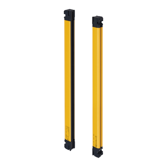
Safety Light Curtain/Safety Multi-Light Beam
F3SG-SR/PG
The most advanced light curtain
• Conforms to major international standards
• Environmental resistance and rugged structure for use in
any environment (IP67, IP67G
• Industry's broadest line-up
from finger protection to body protection
• Flexible height model for easy integration into machines and lines
• For diverse applications, from simple protection to data utilization
*1. IEC 60529/JIS C 0920 Annex 1
*2. Based on Omron investigation in June 2018.
Table of Contents
Model Number Legend ............................................................................................................................................................................... page 2
Ordering Information .................................................................................................................................................................................. page 3
Ratings and Specifications ...................................................................................................................................................................... page 18
List of Models/Response Time/Current Consumption/Weight ............................................................................................................. page 24
Legislation and Standards ....................................................................................................................................................................... page 31
Indicator ..................................................................................................................................................................................................... page 32
Connections (Basic Wiring Diagram)...................................................................................................................................................... page 35
Connectable Safety Control Units ........................................................................................................................................................... page 44
Input/Output Circuit .................................................................................................................................................................................. page 45
Dimensions................................................................................................................................................................................................ page 47
Troubleshooting........................................................................................................................................................................................ page 64
Related Manuals........................................................................................................................................................................................ page 73
All items on this datasheet that
states "Available soon" will be
available in early 2020
1
)
*1
,
*2
For the most recent information on models that have been
certified for safety standards, refer to your local OMRON
website.
Advertisement
Table of Contents

Related Manuals for Omron F3SG-SR/PG


Summary of Contents for Omron F3SG-SR/PG
-
Page 1: Table Of Contents
*1. IEC 60529/JIS C 0920 Annex 1 *2. Based on Omron investigation in June 2018. For the most recent information on models that have been certified for safety standards, refer to your local OMRON website. Table of Contents Model Number Legend ....................................page 2 Ordering Information .................................... -
Page 2: Model Number Legend
F3SG-SR/PG Model Number Legend Safety Light Curtain F3SG-SR F3SG-4SR - - - Classification Code Meaning Remarks Type of ESPE Type 4 Advanced Function Standard 0160 - 2000 Protective height for finger protection (mm) 0160 - 2480... -
Page 3: Ordering Information
Ordering Information Main Units Safety Light Curtain * Emitters and receivers are available separately. For detail, contact your Omron representative. Example 1) Emitter: F3SG-4SRA0160-14-L, receiver: F3SG-4SRA0160-14-D Example 2) Receiver (flexible height model) only: F3SG-4SRA0200-14-D-F Finger protection (Detection capability: 14-mm dia.) - Page 4 F3SG-SR/PG Hand protection (Detection capability: 25-mm dia.) Advanced Standard Protective height Number of beams (mm) Model Model F3SG-4SRA0160-25 F3SG-4SRB0160-25 F3SG-4SRA0200-25-F F3SG-4SRB0200-25-F F3SG-4SRA0240-25 F3SG-4SRB0240-25 F3SG-4SRA0280-25-F F3SG-4SRB0280-25-F F3SG-4SRA0320-25 F3SG-4SRB0320-25 F3SG-4SRA0360-25-F F3SG-4SRB0360-25-F F3SG-4SRA0400-25 F3SG-4SRB0400-25 F3SG-4SRA0440-25-F F3SG-4SRB0440-25-F F3SG-4SRA0480-25 F3SG-4SRB0480-25 F3SG-4SRA0520-25-F F3SG-4SRB0520-25-F F3SG-4SRA0560-25 F3SG-4SRB0560-25 F3SG-4SRA0600-25-F...
- Page 5 F3SG-4SRB0920-85 Safety Multi-Light Beam Available soon * Emitters and receivers (or emitter/receivers and passive mirrors) are available separately. For detail, contact your Omron representative. Example 1) Emitter: F3SG-4PGA0580-2A-L, receiver: F3SG-4PGA0580-2A-D Example 2) Emitter/receiver: F3SG-4PGA0880-3C-LD, passive mirror: F3SG-4PGA0880-3C-M Perimeter access guarding (Beam gap: 300 to 500 mm)
- Page 6 Order the brackets listed below when angle adjustment is required. For F3SG-SR/PG (except for perimeter guarding deflect mirror) The bracket allows beam adjustment after the F3SG-SR/PG (except for perimeter guarding deflect mirror) is mounted on it. Side mounting and backside mounting are possible.
- Page 7 F3SG-SR/PG Safety Light Curtain/Safety Multi-Light Beam Connecting Cable Root-Straight Cable Appearance Type Cable length Specifications Model F39-JG3C-L Brown 24V/0V For emitter Black TEST To sensors: dedicated connector, Blue 0V/24V F39-JG7C-L To external: open-ended type 5 wires White COM(+) Color: Gray...
- Page 8 F3SG-SR/PG Extended Socket-Straight Cable Appearance Type Cable length Specifications Model Connected to root cable or Extended Plug-Socket Cable F39-JG3A-L For emitter Brown 24V/0V M12 connector (5-pin), Black TEST Blue 0V/24V 5 wires White COM(+) Color: Gray Yellow OPERATING RANGE SELECT INPUT/COM(-)
- Page 9 F3SG-SR/PG Side-by-side Cascading Cable (Two cables per set, for emitter and receiver) Appearance Type Cable length Specifications Model For emitter To sensors: dedicated connector 1, To cascading sensors: dedicated connector 2 Used to series-connect sensors with the Color: Gray minimum cable length of 12 cm.
- Page 10 F3SG-SR/PG Conversion Cable Appearance Type Cable length Specifications Model F3SJ-B/A Conversion Cable For emitter To sensor: dedicated connector 1, To wires for F3SJ-B/-A, F3SR or F39-JGR3K-SJ-L F3SN: M12 connector type (8 pin) Used to convert the wiring for F3SJ-B/-A, Color: Gray 0.3 m...
- Page 11 Intelligent Tap Bracket For DIN in Panel F39-LITF1 track. Note: Please contact your OMRON sales representative regarding the IO-Link setup file (IODD file). * Use the F39-SGBT Bluetooth Communication Unit or a commercially available USB Type-C cable to connect to a PC.
- Page 12 F3SG-SR/PG Reduced Wiring System Y-Joint Plug/Socket Connector Appearance Type Cable length Specifications Model F3SG-SR/PG Emitter Receiver Root-Plug Cable for Root-Plug Cable for Extended Extended F39-JGR3K-D (Black) *2 F39-JGR3K-L (Gray) *2 M12 connectors. Used for reduced wiring. 0.5 m F39-GCNY2 Y-Joint Plug/ IP67*1 rated when mated.
- Page 13 Muting Sensor Arm Mounter Bracket for SLC (Two brackets per set, for emitter and receiver) * Appearance Application Model For F3SG-SR/PG (except for perimeter guarding deflect mirror) F39-LMAF1 For F3SG-PG perimeter guarding deflect mirror F39-LMAF2 * Order when mounting the muting sensor arm mounter to the safety light curtain. When the muting sensor arm mounter is mounted to the floor mount column, no brackets are required.
- Page 14 Note: 1. Select the same output type for both the safety light curtain/safety multi-light beam (PNP/NPN selection by wiring) and muting sensor (PNP or NPN model). 2. For details of the XS3W and XS5W, refer to your local OMRON website. 3. Use the F39-JGB-D Extended Plug-Socket Cable to connect the muting sensor connection box with the Intelligent Tap.
- Page 15 F3SG-SR/PG Floor Mount System Available soon Floor Mount Column Protective height of safety light curtain Appearance Column height Model Safety light curtain Safety multi-light beam Up to 0880 0580 990 mm F39-ST0990 Up to 1280 0880, 0980 1,310 mm F39-ST1310...
- Page 16 F3SG-SR/PG Laser Alignment Pointer Appearance Specifications Model The laser alignment pointer is attached on the optical surface of the F3SG-SR/PG to help F39-PTG coarse adjustment of beams. * * Cannot be mounted on the passive mirror. Lamp Available soon Appearance...
- Page 17 F3SG-SR/PG Spatter Protection Cover (2 covers per set, one for emitter and one for receiver) Available soon Safety light curtain Appearance Model Finger protection Hand protection Arm/leg protection F3SG-4SR 0160-14 F3SG-4SR 0160-25 F39-HSG0160 F39-HSG0240 F3SG-4SR 0240-14 F3SG-4SR ...
-
Page 18: Ratings And Specifications
F3SG-SR/PG Ratings and Specifications Safety Light Curtain F3SG-SR Series Main unit The in the model names indicate the protective heights in millimeters. F3SG- F3SG- F3SG- F3SG- Model F3SG- F3SG- ... - Page 19 F3SG-SR/PG F3SG- F3SG- F3SG- F3SG- Model F3SG- F3SG- F3SG- F3SG- Light emission stops when connected to 24 V DC ON voltage: Vs-3 V to Vs (short circuit current: approx. 5.0 mA) * OFF voltage: 0 V to 1/2 Vs, or open (short circuit current: approx.
- Page 20 F3SG-SR/PG F3SG- F3SG- F3SG- F3SG- Model F3SG- F3SG- F3SG- F3SG- M12 connector type (5-pin emitter and 8-pin receiver), IP67 * rated when mated Type of...
- Page 21 F3SG-SR/PG Restrictions on cable extension For the cable extension of the F3SG-SR, refer to the following diagrams. For the cable extension of the F3SG-SR with the Intelligent Tap, refer to User's Manual. - Wired synchronization Maximum extension length Emitter (1) to (4): 10 m each *...
- Page 22 F3SG-SR/PG Intelligent Tap F39-SGIT-IL3 Model F39-SGIT-IL3 Applicable sensor F3SG-SR Series Output ON to OFF and OFF to ON: 44 ms max. each * Response time Performance * The response time is the time interval between the changes of the states of the sensor OSSD's and the DO (pin 2).
- Page 23 F3SG-SR/PG Bluetooth Communication Unit ® Model F39-SGBT Applicable sensor F3SG-SR Series Power supply voltage (Vs) 24 VDC±20%, ripple p-p 10% max. (shares power supply of Intelligent Tap) Current consumption 30 mA max. (shares power supply of Intelligent Tap) Operating: -30 to 55 °C (non-icing) Ambient temperature Storage: -30 to 70 °C...
-
Page 24: List Of Models/Response Time/Current Consumption/Weight
F3SG-SR/PG List of Models/Response Time/Current Consumption/Weight F3SG-SR Finger protection (Detection capability: 14-mm dia.) List of Models and Response Times Response time Response time (Wired (Optical synchronization) [ms] synchronization) Number of Protective [ms] Model beams height [mm] OFF (not ON to... - Page 25 F3SG-SR/PG List of Models, Current Consumption and Weight Current consumption [mA] Weight [kg] Protective height Model Number of beams [mm] Emitter Receiver Gross F3SG-4SRA0160-14 F3SG-SRB0160-14 F3SG-4SRA0200-14-F F3SG-4SRB0200-14-F F3SG-4SRA0240-14 F3SG-SRB0240-14 F3SG-4SRA0280-14-F F3SG-4SRB0280-14-F F3SG-4SRA0320-14 F3SG-SRB0320-14 F3SG-4SRA0360-14-F F3SG-4SRB0360-14-F F3SG-4SRA0400-14 F3SG-SRB0400-14 F3SG-4SRA0440-14-F F3SG-4SRB0440-14-F F3SG-4SRA0480-14 F3SG-SRB0480-14...
- Page 26 F3SG-SR/PG Hand protection (Detection capability: 25-mm dia.) List of Models and Response Times Response time Response time (Wired (Optical synchronization) [ms] synchronization) Number of Protective [ms] Model beams height [mm] OFF (not ON to ON to OFF to (synchronized) synchronized)
- Page 27 F3SG-SR/PG List of Models, Current Consumption and Weight Current consumption [mA] Weight [kg] Number of Protective Model beams height [mm] Emitter Receiver Gross F3SG-4SRA0160-25 F3SG-SRB0160-25 F3SG-4SRA0200-25-F F3SG-4SRB0200-25-F F3SG-4SRA0240-25 F3SG-SRB0240-25 F3SG-4SRA0280-25-F F3SG-4SRB0280-25-F F3SG-4SRA0320-25 F3SG-SRB0320-25 F3SG-4SRA0360-25-F F3SG-4SRB0360-25-F F3SG-4SRA0400-25 F3SG-SRB0400-25 F3SG-4SRA0440-25-F F3SG-4SRB0440-25-F F3SG-4SRA0480-25 F3SG-SRB0480-25...
- Page 28 F3SG-SR/PG Current consumption [mA] Weight [kg] Number of Protective Model beams height [mm] Emitter Receiver Gross F3SG-4SRA1440-25 1440 F3SG-SRB1440-25 1440 F3SG-4SRA1520-25 1520 F3SG-SRB1520-25 1520 F3SG-4SRA1600-25 1600 F3SG-SRB1600-25 1600 F3SG-4SRA1680-25 1680 F3SG-SRB1680-25 1680 F3SG-4SRA1760-25 1760 F3SG-SRB1760-25 1760 F3SG-4SRA1840-25 1840 F3SG-SRB1840-25 1840...
- Page 29 F3SG-SR/PG Arm/leg protection (Detection capability: 45-mm dia.) List of Models and Response Times Response time Response time (Wired (Optical synchronization) [ms] synchronization) Number of Protective [ms] Model beams height [mm] OFF (not ON to ON to OFF to (synchronized) synchronized)
- Page 30 F3SG-SR/PG Body protection (Detection capability: 85-mm dia.) List of Models and Response Times Response time Response time (Wired (Optical synchronization) [ms] synchronization) Number of Protective [ms] Model beams height [mm] OFF (not ON to ON to OFF to (synchronized) synchronized)
-
Page 31: Legislation And Standards
6. Other Standards The F3SG-SR/PG is designed according to the standards listed below. To make sure that the final system complies with the following standards and regulations, you are asked to design and use it in accordance with all other related standards, laws, and regulations. If you have any questions, consult with specialized organizations such as the body responsible for prescribing and/or enforcing machinery safety regulations in the location where the equipment is to be used. -
Page 32: Indicator
F3SG-SR/PG Indicator LED Indicators on F3SG-SR Shown below are indication statuses of the LED indicators on the F3SG-SR when you purchased. Emitter (F3SG-SR) Location Indicator Name Color Illuminated Blinking F3SG-SRA F3SG-SRB Green Code A is selected Orange Code B is selected... - Page 33 F3SG-SR/PG Receiver (F3SG-SR) Location Indicator Name Color Illuminated Blinking F3SG-SRA F3SG-SRB Green Code A is selected Orange Code B is selected Scan code Automatic interference prevention by wired synchronization being CODE performed LOCKOUT state. The indicator is illuminated in the receiver of another LOCKOUT state.
- Page 34 F3SG-SR/PG LED Indicators on Intelligent Tap Shown below are indication statuses of LED indicators on the Intelligent Tap when you purchased. Location Indicator Name Color Illuminated Blinking The F3SG-SR is in the LOCKOUT state. Or the Intelligent Tap is waiting for Push Switch...
-
Page 35: Connections (Basic Wiring Diagram)
F3SG-SR/PG Connections (Basic Wiring Diagram) F3SG-SR Examples of a motor control system using the F3SG-SR are shown below. The examples are equivalent to up to PLe, Category 4 (ISO 13849-1). Non-Muting System Wiring Examples Auto Reset Mode with Optical Synchronization and EDM Unused... - Page 36 F3SG-SR/PG Auto Reset Mode with Wired Synchronization and EDM Unused [Wiring Example] Intelligent Tap Not needed F39-JG C-L F39-JG C-D Wiring for NPN * 1 24 VDC 24 VDC Safety controller * 4 * 5 Function Setting EDM Disabled (factory default setting)
- Page 37 F3SG-SR/PG Manual Reset Mode with EDM [Wiring Example] Intelligent Tap Needed F39-JG C-L F39-JG C-D Wiring for NPN * 1 24 VDC 24 VDC : Indicates a switch position. Setting Function DIP switch SD Manager 3 EDM *4 EDM Enabled...
- Page 38 F3SG-SR/PG Manual Reset Mode with EDM and Y-Joint Plug/Socket Connector [Wiring Example] Intelligent Tap Needed F39-JGR3K-D and F39-JG□B-D F39-GCNY2 F39-JGR3K-L and F39-JG□B-L F39-JG A-D Wiring for NPN * 1 24 VDC 24 VDC PLC * 2 : Indicates a switch position.
- Page 39 F3SG-SR/PG Manual Reset Mode with Intelligent Tap [Wiring Example] Intelligent Tap Needed F39-JGR3K-L and F39-JGR3K-D and F39-JG□B-D F39-JG□B-L F39-SGIT-IL3 F39-JG B-L/ XS5F-D521-DJ0-IL IO-Link Master * 5 F39-JG A-D Wiring for NPN * 1 24 VDC 24 VDC Safety controller PLC * 2 * 3 * 4 ...
- Page 40 F3SG-SR/PG Manual Reset Mode with Reset Switch Connector [Wiring Example] Innteligent Tap Needed F39-JGR3K-D F39-GCNY3 F39-JG C-L XS5F-D421 80-F F39-JG A-D Wiring for NPN * 1 24 VDC 24 VDC Safety controller * 3 * 4 : Indicates a switch position.
- Page 41 F3SG-SR/PG Double Break with EDM [Wiring Example] Needed * 5 Intelligent Tap F39-JG C-L F39-JG C-D Wiring for NPN * 1 0 VDC 24 VDC 24 VDC PLC * 3 : Indicates a switch position. Setting Function DIP switch SD Manager 3...
- Page 42 F3SG-SR/PG Muting System Wiring Examples Standard Muting Mode/Exit-Only Muting mode [Wiring Example] Needed *9 Intelligent Tap F39-JG C-L F39-JG C-D Wiring for NPN * 1 24 VDC 24 VDC S1: Test switch S2: Lockout reset switch, override switch or override cancel switch S3, S4: Muting sensor PLC: Programmable logic controller (Used for monitoring only.
- Page 43 F3SG-SR/PG Standard Muting Mode/Exit-Only Muting mode with Intelligent Tap [Wiring Example] Intelligent Tap Needed F39-SGIT-IL3 F39-JGR3K-L and F39-JG□B-L F39-JGR3K-D and F39-JG B-L/ F39-JG□B-D XS5F-D521-DJ0-IL IO-Link Master * 7 F39-JG A-D Wiring for NPN * 1 24 VDC 24 VDC Safety controller...
-
Page 44: Connectable Safety Control Units
F3SG-SR/PG Connectable Safety Control Units The F3SG-SR in the PNP system can be connected to the safety control units listed in the table below. Connectable safety control units (PNP output) G9SA-301 G9SX-AD322-T G9SP-N10S G9SA-321-T G9SX-ADA222-T G9SP-N10D G9SA-501 G9SX-BC202 G9SP-N20S G9SB-200-B... -
Page 45: Input/Output Circuit
F3SG-SR/PG Input/Output Circuit Entire Circuit Diagram The entire circuit diagrams of the F3SG-SR are shown below. The numbers in the circles indicate the connector's pin numbers. F3SG-SR Indicator PNP/NPN select input circuit Brown 24V/0V Test input Black TEST circuit Emitter... - Page 46 F3SG-SR/PG Input Circuit Diagram by Function The input circuit diagrams of by function are shown below. Test Input <Light emission stops when connected to 24 VDC> <Light emission stops when connected to 0 V> +24 VDC +24 VDC Short circuit...
-
Page 47: Dimensions
F3SG-SR/PG Dimensions (Unit: mm) F3SG-SR Series Mounted with Side-Mount Brackets (Intermediate Brackets) (F39-LSGF) Backside Mounting 46.7 Side-Mont Bracket (F39-LSGF) 2-M5 or M6 Side-Mont Bracket (F39-LSGF) 2-M5 or M6 <Screw: M5 or M6> Dimension C 4-digit number of the type name (Protective height: ... - Page 48 F3SG-SR/PG Side Mounting Side-Mont Bracket (F39-LSGF) 2-M5 or M6 Side-Mont Bracket (F39-LSGF) 2-M5 or M6 19.4 <Screw: M5 or M6> 46.7 Dimension C 4-digit number of the type name (Protective height: ) F3SG-SR-14 C-20 F3SG-SR-25 Dimension D F3SG-SR-45 C-40 F3SG-SR-85 F3SG-SR-14...
- Page 49 F3SG-SR/PG Mounted with Adjustable Side-Mount Brackets (Intermediate Brackets) (F39-LSGA) Backside Mounting 46.7 Adjustable Side-Mount Bracket (F39-LSGA) 2-M5 or M6 Adjustable Side-Mount Bracket (F39-LSGA) 2-M5 or M6 <Screw: M5 or M6> Dimension C 4-digit number of the type name (Protective height: ) F3SG-SR-14...
- Page 50 F3SG-SR/PG Side Mounting Adjustable Side-Mount Bracket 2-M5 (F39-LSGA) or M6 Adjustable Side-Mount Bracket 23.5 (F39-LSGA) 2-M5 or M6 <Screw: M5 or M6> 46.7 Dimension C 4-digit number of the type name (Protective height: ) F3SG-SR-14 C-20 F3SG-SR-25 Dimension D F3SG-SR-45 C-40 F3SG-SR-85...
- Page 51 F3SG-SR/PG Mounted with Adjustable Top/Bottom Brackets (F3SJ, F3SN Adapter) (F39-LSGTB-SJ) and Side-Mount Brackets (Intermediate Brackets) (F39-LSGF) Backside Mounting 46.7 2-M8 Adjustable 4-M5 Top/Bottom Bracket (F39-LSGTB-SJ) Side-Mont Bracket (F39-LSGF) 2-M5 2-M5 or M6 or M6 Adjustable Top/Bottom Bracket (F39-LSGTB-SJ) <Screw for Adjustable <Screw for Adjustable...
- Page 52 F3SG-SR/PG Side Mounting 2-M8 4-M5 Adjustable Top/Bottom Bracket (F39-LSGTB-SJ) Side-Mont Bracket (F39-LSGF) 2-M5 2-M5 or M6 or M6 Adjustable Top/Bottom Bracket (F39-LSGTB-SJ) <Screw for Adjustable <Screw for Adjustable Top/Bottom Bracket: M5 *1> Top/Bottom Bracket: M8 *1> 46.7 Dimension C 4-digit number of the type name (Protective height: ) F3SG-SR-14...
- Page 53 F3SG-SR/PG Mounted with Adjustable Top/Bottom Brackets (F3SJ, F3SN Adapter) (F39-LSGTB-SJ) and Adjustable Side-Mount Brackets (Intermediate Brackets) (F39-LSGA) Backside Mounting 46.7 2-M8 4-M5 Adjustable Top/Bottom Bracket (F39-LSGTB-SJ) Adjustable Side-Mount Bracket (F39-LSGA) 2-M5 2-M5 or M6 or M6 Adjustable Top/Bottom Bracket (F39-LSGTB-SJ) <Screw for Adjustable...
- Page 54 F3SG-SR/PG Side Mounting 2-M8 Adjustable Top/Bottom 4-M5 Bracket (F39-LSGTB-SJ) Adjustable Side-Mount Bracket (F39-LSGA) 2-M5 2-M5 or M6 or M6 Adjustable Top/Bottom Bracket (F39-LSGTB-SJ) <Screw for Adjustable <Screw for Adjustable Top/Bottom Bracket: M8 *1> Top/Bottom Bracket: M5 *1> 46.7 Dimension C 4-digit number of the type name (Protective height: )
- Page 55 F3SG-SR/PG Accessories Bracket Side-Mount Bracket (Intermediate Bracket) (F39-LSGF) 34.4 Material: Zinc alloy Adjustable Side-Mount Bracket (Intermediate Bracket) (F39-LSGA, sold separately) 56.5 56.5 Material: Zinc alloy Adjustable Top/Bottom Bracket (F3SJ, F3SN Adapter) (F39-LSGTB-SJ, sold separately) 47.7 Material: High rolled steel (SPHC)
- Page 56 F3SG-SR/PG Adjustable Top/Bottom Bracket (F3SG-RA/RE Adapter) (F39-LSGTB-RE, sold separately) 47.7 Material: High rolled steel (SPHC) Adjustable Top/Bottom Bracket (MS4800, F3SR Adapter) (F39-LSGTB-MS, sold separately) 47.7 38.1 52.8 Material: High rolled steel (SPHC)
- Page 57 F3SG-SR/PG Intelligent Tap Intelligent Tap (F39-SGIT-IL3, sold separately) 2-M4 <Screw: M4> M12 IP67 M12 IP67 11.9 17.5 17.5 connector connector M12 IP67 M12 IP67 connector connector Material: PBT resin (Body parts) Intelligent Tap Bracket (F39- LITF1, sold separately) (105) 2-M4 Mounting dimensions to DIN track 30.3...
- Page 58 F3SG-SR/PG Assembly Dimensions (Intelligent Tap/ Intelligent Tap Bracket) <Mounting on DIN track> Intelligent Tap F39-SGIT-IL3 30.3 Intelligent Tap Bracket 47.8 F39-LITF1 Material: PBT resin (Body parts) Bluetooth Communication Unit (F39-SGBT, sold separately) ® 19.7 40.7 Material: PBT resin (Body parts)
- Page 59 F3SG-SR/PG Spatter Protection Cover Spatter Protection Cover (F39-HSG, sold separately) Assembly Dimensions 34.2 11.1 L = @@@@ Material: PC resin (Transparent cover) ABS resin (Side wall) Connecting cable Root-Straight Cable Root -Straight Cable for Emitter (F39-JGC-L, sold separately) 16.4 2-M2.5 screw 31.6...
- Page 60 F3SG-SR/PG Extended Socket-Straight Cable Extended Socket-Straight Cable for Emitter (F39-JGA-L, sold separately) 40.7 Insulated vinyl round cable, dia. 6.6, minimum bending radius R36, 5-wire (Cross section of conductor: 0.32 mm /insulator diameter: dia. 1.2 mm/AWG22) M12 IP67 connector Extended Socket-Straight Cable for Receiver (F39-JGA-D, sold separately) 40.7...
- Page 61 F3SG-SR/PG Cascading Cable for Extended (F39-JGR3W, sold separately) (two cables per set, one for emitter and one for receiver) Emitter Cascading Cable for Extended 2-M2.5 screw 16.4 40.7 31.6 M12 IP67 Connector Connector Oil-resistant PVC-insulated round cable, dia. 6 minimum bending radius R5, 5-wire (Cross section of conductor: 0.2 mm...
- Page 62 F3SG-SR/PG F3SJ-B/A Conversion Cable for Receiver (F39-JGR3K-SJ-D, sold separately) 2-M2.5 screw 16.4 44.7 31.6 M12 IP67 connector, 8-wire Oil-resistant PVC-insulated round cable, dia. 6 Connector minimum bending radius R5 (Cross section of conductor: 0.2 mm /insulator diameter: dia. 1.1 mm)
- Page 63 F3SG-SR/PG Y-Joint Plug/Socket Connector (F39-GCNY2, sold separately) Plug marked with (blue circle): Connect to control panel side Socket marked with (open circle): Connect to emitter 15.0 17.7 45.5 40.7 To control panel side To receiver To emitter Insulated vinyl round cable, dia. 6...
-
Page 64: Troubleshooting
F3SG-SR/PG Troubleshooting F3SG-SR LOCKOUT State Identify an error according to the combination of the indicators when the error occurs. See the following troubleshooting tables to take measures. For detail, Refer to User’s Manual. Illuminated Blink <Indicator status at lockout: Receiver>... - Page 65 F3SG-SR/PG Checking by Error code SD Manager 3/ Description Cause and measures (HEX) Indicator SD Manager 3 Mobile APP The OSSD lines may be short-circuited to each other or another signal line may be short-circuited to the OSSD 60, 6B, 6C line.
- Page 66 F3SG-SR/PG Checking by Error code SD Manager 3/ Description Cause and measures (HEX) Indicator SD Manager 3 Mobile APP Cap error A cap may be detached. Attach the cap properly. Other sensor being cascaded caused an error. Check the Other sensor error indicator of the sensor.
- Page 67 F3SG-SR/PG Checking by Error code SD Manager 3/ Description Cause and measures (HEX) Indicator SD Manager 3 Mobile APP The setting of the operating range selection may be incorrect. • When the Intelligent Tap is connected, check if the Operating range selection setting...
- Page 68 F3SG-SR/PG Warning Identify an error according to the combination of the indicators when the error occurs. See the following troubleshooting tables to take measures. For detail, Refer to User’s Manual. Blinking Illuminated <Indicator status at warning: Receiver *1> Combination of indicators and error description...
- Page 69 F3SG-SR/PG Muting Sequence Error Indication The following table is applied only when the muting function is being enabled. SEQ indicator Cause and measures Power supply may have been turned ON with muting input A or B being ON. Check the condition of the muting sensors and the F3SG-SR.
- Page 70 F3SG-SR/PG PSDI Sequence Error Indication The following table is applied only when the PSDI function is being enabled. Error SEQ indicator Cause and measures condition Power supply may have been turned ON with PSDI input being OFF. Check the condition of the light curtains and PSDI input wiring.
- Page 71 F3SG-SR/PG Intelligent Tap If the Intelligent Tap detects any failure, it transitions to the LOCKOUT state. Under the LOCKOUT state, the ERR indicator is turned ON. Identify an error according to the combination of the indicators when the error occurs. See the following troubleshooting tables to take measures.
- Page 72 F3SG-SR/PG Checking by Error SD Manager 3/ Description code Cause and measures Indicator SD Manager 3 (HEX) * Mobile APP The communication lines or other lines may be short-circuited or broken. Check the cables for cascading or extension cables. If the wiring is extended with cables other than specified, the cables used for extension may not have performance equivalent or greater than the specified cables.
-
Page 73: Related Manuals
• The Bluetooth ® word mark and logo are registered trademarks and are owned by the Bluetooth SIG, Inc. and any use of such mark by OMRON Corporation is under license. • USB Type-C™ is a trademark of USB Implementers Forum. - Page 74 OMRON AUTOMATION AMERICAS HEADQUARTERS • Chicago, IL USA • 847.843.7900 • 800.556.6766 • automation.omron.com OMRON CANADA, INC. • HEAD OFFICE OMRON ELETRÔNICA DO BRASIL LTDA • HEAD OFFICE Toronto, ON, Canada • 416.286.6465 • 866.986.6766 • automation.omron.com São Paulo, SP, Brasil • 55.11.2101.6300 • www.omron.com.br OMRON ELECTRONICS DE MEXICO •...
- Page 75 Safety Light Curtains Click to view products by manufacturer: Omron Other Similar products are found below : F39JA1C F39-PTJ SF4D-H32 42370 NA1-PK3 SFB-CCB3 SF4C-H32 SF4C-F31 MS-SFD-1-5 SF4D-TM1 SFD-CCB10-S SFD-CCB3 SFD-CCB5-S SFD-CCB7 SF4D-H12 SF4D-H16 40636-0010 SLSP30-900Q88 MS-SFB-1 F39LGRA F39LGRTB F39LGRTB2...
Need help?
Do you have a question about the F3SG-SR/PG and is the answer not in the manual?
Questions and answers