
Related Manuals for Omron F3SG-4RA****-25-01TS Series


Summary of Contents for Omron F3SG-4RA****-25-01TS Series
- Page 1 F3SG-4RA -25-01TS http://www.ia.omron.com/f3sg-r © OMRON Corporation 2016 All Rights Reserved. Original instructions...
-
Page 2: Table Of Contents
こ のたびはセー フ テ ィ ラ イ ト カ ーテ ン形 F3SG-4RA □□□□ -25-01TS シ リ ーズ ( 以下 F3SG-RA と 呼びま す ) を お買い上げいただ き、 あ り が と う ご ざいます。 本書は F3SG-RA の設置についての簡易説明書です。 F3SG-RA の取扱説明書の全文は下記の当社ウ ェ ブサイ ト よ り ダウン ロー ド し て く だ さ い。 http://www.ia.omron.com/f3sg-r 目次 1. 同梱物のご確認....................................1 2. 各部の名称......................................2 3. -
Page 3: 各部の名称
2. 各部の名称 3. ラ イ ト カ ーテ ン セ ッ ト ア ッ プ手順例 ..3 ページ ..4 ページ ..5 ページ ..12 ページ * DIP-SW の設定は必要に応 じ て実施 し て く だ さ い。 F3SG-4RA-25-01TS ク... -
Page 4: Dip-Sw 設定
4. DIP-SW 設定 □ ス イ ッ チポジ シ ョ ン を表 し ます。 設定 チ ャ ン ネル 機能 出荷時設定 概要 DIP-SW1 DIP-SW2 ○ スキ ャ ン コ ー ド A スキ ャ ン コ ー ド スキ ャ ン コ ー ド B ○... -
Page 5: 配線例
5. 配線例 ユーザーズマニ ュ アル 入出力回路および下記以外の配線例については、 を参照し て く だ さ い。 5-1. EDM 無効、 外部テ ス ト 未使用、 PNP 出力 F39-JD A-L F39-JD A-D +DC24V セーフティ *3 *4 コントローラ *1. 各種機能をDIP-SWで設定可能です。 詳細は4. DIP-SW設定を参照 し て く だ さ い。 *2. -
Page 6: 取 り つけ ・ 光軸調整
DIP-SW 設定 配線 取りつけ ・ 光軸調整 動作チェック Step1 取りつけ 位置確認 2-S3 Step2 26.5 上下調整金具 48.6 (形F39-LGTB) 23.2 2-M5またはM6 2-M8 取りつけ 背面:2-S3 Step3 40.8 光軸調整 13.6 S2.5 標準調整金具 (形F39-LGA) 2-M5またはM6 2-M5またはM6 24.85 24.85 24.85 上下調整金具 (形F39-LGTB) <上下調整金具のM5またはM6固定> <上下調整金具のM8固定> F3SG- RA F3SG-4RA-25-01TS... - Page 7 ■外形寸法図 (形 F3SG-4RA0185-25-01TS の場合) [ 背面取 り つけ時 ] [ 単位 : mm ] 形F3SG-4RA0185-25-01TS ア ク セサ リ 接続時*1 ア ク セサ リ 形F39-LP 非接続時 形F39-JGR2WTS 形F39-BT 形F39-BTLP 寸法C 同左 寸法D 同左 寸法G 277.5 同左 寸法H 277.5 292.5 寸法I 306.5 寸法P 同左...
- Page 8 ■取 り つけ方法 と 光軸調整 1. ボル ト を緩め角度を調整 し ます。 ボル ト (1),(2) と も に六角穴サイ ズはS=3です。 2. 取付け位置を調整 し 固定 し ます。 F3SG-R の筐体 (黄色のエ リ ア) 内に上下金具 (1) の全体が位置する よ う に固定 し て く だ さ い。 ( 推奨締め付け...
- Page 9 4. 表示灯を参考に光軸を調整 し ます。 上下調整金具の角度調整範囲は±22.5°です。 6. 残 り のボル ト を本締め し ます。 ( 推奨締め付け ト ルク 3.0N ・ m) F3SG-4RA-25-01TS ク イ ッ ク イ ンス ト ールマニ ュ アル...
-
Page 10: 標準調整金具 ( 形 F39-Lga) を取 り つける場合
6-2. 標準調整金具 ( 形 F39-LGA) を取 り つける場合 ■外形寸法図 (取 り つけ位置確認) [ 背面取 り つけ時 ] < M5 または M6 固定 > [ 単位 : mm ] 形 F3SG-4RA □□□□ -25-01TS シ リ ーズ 寸法A C+23 寸法C 形式中の4桁の数字 (検出幅) 寸法D C-45 寸法P... - Page 11 ■取 り つけ方法 と 光軸調整 1. ボル ト を緩め角度を調整 し ます。 2. ボル ト を仮締め し ます。 3. 取 り つけ位置を調整 し 固定 し ます。 4. 壁面に固定 し ます。 壁面 と の取 り つけネジは付属 し ていません。 F3SG-4RA-25-01TS ク イ ッ ク イ ンス ト ールマニ ュ アル...
- Page 12 5. 表示灯を参考に光軸を調整 し ます。 標準調整金具の角度調整範囲は±15°です。 6. 残 り のボル ト を本締め し ます。 F3SG-4RA-25-01TS ク イ ッ ク イ ンス ト ールマニ ュ アル...
-
Page 13: 動作チ ェ ッ ク
●製品に関するお問い合わせ先 お客様相談室 クイック オムロン 0120-919-066 携帯電話 ・ PHS ・ IP電話な ど ではご利用いただけませんので、 下記の電話番号へおかけ く だ さ い。 055-982-5015 電話 (通話料がかかり ます) ■営業時間:8:00∼21:00 ■営業日:365日 ●FAXやWebページでもお問い合わせいただけます。 055-982-5051 / www.fa.omron.co.jp ●その他のお問い合わせ 納期・価格・サンプル・仕様書は貴社のお取引先、または貴社担当オムロン販売員にご相談ください。 オムロン制御機器販売店やオムロン販売拠点は、Webページでご案内しています。 F3SG-4RA-25-01TS ク イ ッ ク イ ンス ト ールマニ ュ アル... - Page 14 Safety Light Curtain □□□□ F3SG-4RA -25-01TS Series http://www.ia.omron.com/f3sg-r Quick Installation Manual Document Title Cat. No. Safty Light Curtain F3SG-4RA-25-01TS Series Z380-E1 User's Manual © OMRON Corporation 2016 All Rights Reserved. 5132821-8B Original instructions...
-
Page 15: What Is Included
Thank you for purchasing the F3SG-4RA-25-01TS Series Safety Light Curtain (hereinafter referred to as the "F3SG-RA"). This document contains simple instructions to install the F3SG-RA. Please download the F3SG-RA User's Manual for full contents of the instructions from our website at: http://www.ia.omron.com/f3sg-r Table of Contents 1. What is Included..........................1 2. -
Page 16: System Components
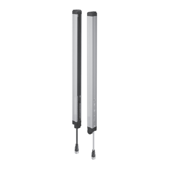
2. System Components <Emitter> <Receiver> Beam center-line mark Beam 1. TOP indicator (Blue) Emitter 2. NPN indicator (Green) Indicator Receiver DIP Switch (Emitter) 3. CFG indicator (Green) 1. Test indicator (Green) 2. LONG indicator (Green) 4. EDM indicator (Green) 3. Power indicator (Green) DIP Switch (Receiver) 5. -
Page 17: Setting With Dip Switch
Setting with DIP Switch Wiring Mounting/Beam Alignment Operation check 4. Setting with DIP Switch Step 1 Step 2 Step 3 DIP Switch Receiver Emitter Screw(M2.5) Screw(M2.5) Tightening torque: 0.35 N•m (recommended) Open the cover Change the settings (See below) Close the cover : Indicates a switch position. -
Page 18: Wiring Examples
Setting with DIP Switch Wiring Mounting/Beam Alignment Operation check 5.Wiring Examples For input/output circuit and other examples than below, refer to User's Manual. 5-1. EDM disabled, External Test disabled and PNP Outputs F39-JD A-L F39-JD A-D +DC24V Safety Controller *3 *4 *1. -
Page 19: Mounting And Beam Alignment
Setting with DIP Switch Wiring Mounting/Beam Alignment Operation check 6. Mounting and Beam Alignment 6-1. Mounted with Top/Bottom Adjustable Brackets (F39-LGTB) and Stan- Step1 dard Adjustable Brackets (F39-LGA) ■ Check Dimensions (F3SG-RA Series Except F3SG-4RA0185-25-01TS) position [Backside mounting] 2-S3 Step2 Top/Bottom Mount Adjustable Bracket... - Page 20 Setting with DIP Switch Wiring Mounting/Beam Alignment Operation check ■ Dimensions (F3SG-4RA0185-25-01TS) [Backside mounting] 2-S3 Step1 Check position Top/Bottom Adjustable Bracket 26.5 Step2 48.6 (F39-LGTB) 23.2 2-M5 or M6 2-M8 Mount 13.6 Backside : 2-S3 Step3 40.8 Align beams Top/Bottom Adjustable Bracket (F39-LGTB) <Screw for Top/Bottom Adjustable...
- Page 21 Setting with DIP Switch Wiring Mounting/Beam Alignment Operation check ■ Mounting and Beam Alignment 1. Loosen the screws and adjust the angle. Screw (2) Step1 (Low head hexagon socket head cap screw (M5×10)) Check position Screw (1) (Hexagon socket head cap screw (M4×10)) Top/Bottom Step2...
- Page 22 Setting with DIP Switch Wiring Mounting/Beam Alignment Operation check 4. Perform beam alignment according to the indicators. <Emitter> <Receiver> <Receiver> <Receiver> Step1 TOP(Blue) TOP(Blue) Check position Step2 Mount Stable-state(Green) Stable-state(Green) Step3 BTM(Blue) BTM(Blue) Align beams Angle adjustment range: ±22.5° 5. Securely tighten the remaining screws. <Backside mounting >...
-
Page 23: Mounting With Standard Adjustable Brackets (F39-Lga)
Setting with DIP Switch Wiring Mounting/Beam Alignment Operation check 6-2. Mounting with Standard Adjustable Brackets (F39-LGA) ■ Dimensions (Check position) [Backside mounting] Step1 Check position 48.6 Step2 Mount 2-M5 or M6 Standard Adjustable Bracket Step3 (F39-LGA) Align beams Standard Adjustable Bracket (F39-LGA) 2-M5 or M6... - Page 24 Setting with DIP Switch Wiring Mounting/Beam Alignment Operation check ■ Mounting and Beam Alignment 1. Loosen the screws and adjust the angle. hexagon socket head Step1 cap screw (M3 x 15) Check position hexagon socket head hook cap screw (M3 x 15) Step2 Mount 2.
- Page 25 Setting with DIP Switch Setting with DIP Switch Wiring Wiring Mounting/Beam Alignment Mounting/Beam Alignment Operation check Operation check 5. Perform beam alignment according to the indicators. <Emitter> <Receiver> <Receiver> <Receiver> Step1 TOP(Blue) TOP(Blue) Check position Step2 Mount Stable-state(Green) Stable-state(Green) Step3 BTM(Blue) BTM(Blue) Align...
-
Page 26: Operation Check
Omron Companies shall not be responsible for conformity with any standards, codes or regulations which apply to the combination of the Product in the Buyer’s application or use of the Product. At Buyer’s request, Omron will provide applicable third party certification documents identifying ratings and limitations of use which apply to the Product. This information by itself is not sufficient for a complete determination of the suitability of the Product in combination with the end product, machine, system, or other application or use.
Need help?
Do you have a question about the F3SG-4RA****-25-01TS Series and is the answer not in the manual?
Questions and answers