Table of Contents
Advertisement
Quick Links
FRESH AIR VENTILATION CONTROL
The Field Controls Fresh Air Ventilation Control
year-round, keeping energy conservation, indoor air quality and comfort in mind. The FAVC delivers
ventilation along with many additional features:
• Meets the requirements of the ASHRAE 62.2 standard for ventilation.
• Supplied with an outdoor temperature sensor which mounts in the fresh air duct.
• Has three selectable Climate Zones with unique ventilation inhibit parameters for the selected
climate.
• Monitors up to four exhaust appliances within your home to adjust ventilation needs based on
total appliance operation.
• Can provide Make-Up air in response to an exhausting appliance.
• Can utilize an exhaust fan to drive ventilation independent of the central HVAC fan to save energy.
• Continuously monitors indoor Relative Humidity:
- Lower excess indoor humidity during hot muggy days by reducing ventilation during
these periods to prevent discomfort and mold growth in the home.
- Reduce condensation and corrosion of the heat exchanger.
READ THESE INSTRUCTIONS CAREFULLY AND COMPLETELY BEFORE PROCEEDING WITH THE INSTALLATION.
READ THESE INSTRUCTIONS CAREFULLY AND COMPLETELY
This device MUST be installed by a qualifi ed agency in accordance with the manufacturer's installation instructions. The defi nition of
a qualifi ed agency is: any individual, fi rm, corporation or company which either in person or through a representative is engaged
in, and is responsible for, the installation and operation of HVAC appliances, who is experienced in such work, familiar with all the
precautions required, and has complied with all the requirements of the authority having jurisdiction.
Installed By:
Model: FAVC
TM
(FAVC) is designed to provide fresh air ventilation
Please retain these instructions after installation.
Phone:
www.fi eldcontrols.com
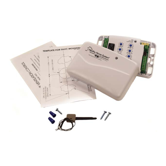
ITEMS INCLUDED:
1 – Fresh Air Ventilation Controller
1 – Mounting Hole Template
1 – Instruction and Installation Manual
1 – Mounting Packet containing
two (2) Sheet Metal Screws
1 – ODT Sensor Packet containing
temperature sensor, sheet metal
screw and two (2) wire nuts
BEFORE PROCEEDING WITH THE INSTALLATION.
Installation Date:
P/N 780100700 07/18 Rev F
Advertisement
Table of Contents

Related Manuals for Field Controls FAVC


Summary of Contents for Field Controls FAVC
- Page 1 The Field Controls Fresh Air Ventilation Control (FAVC) is designed to provide fresh air ventilation year-round, keeping energy conservation, indoor air quality and comfort in mind. The FAVC delivers ventilation along with many additional features: • Meets the requirements of the ASHRAE 62.2 standard for ventilation.
- Page 2 (THIS PAGE LEFT INTENTIONALLY BLANK) Page 2 of 36 P/N 780100700 07/18 Rev F...
-
Page 3: Table Of Contents
TABLE OF CONTENTS page 1. FAVC LAYOUT - OVERVIEW 2. GATHER INFORMATION/ RECORD/ SET CONTROL Determine The Required CFM Continuous Residential Ventilation Determine Fresh Air Intake 3. INHIBIT SET-UP - Dip Switches 1 & 2 Climate Zone Inhibit Options Normal Climate Zone... - Page 4 • Do not mount the FAVC controller on the supply plenum or supply ductwork. • Do not mount the FAVC controller immediately downstream from any fresh air intake port, humidifi er or bypass outlet. False humidity conditions will cause the FAVC controller to operate incorrectly.
-
Page 5: Favc Layout - Overview
1. FAVC LAYOUT - OVERVIEW Page 5 of 36 P/N 780100700 07/18 Rev F... -
Page 6: Gather Information/Record/Set Control
1. Turn the dials of the heat vent and cool vent back to the desired value as marked or noted previously. 2. The FAVC will begin to ventilate on a cycle per the settings. 2A. DETERMINE THE REQUIRED CFM CONTINUOUS RESTIDENTIAL VENTILATION 1. - Page 7 Number of Bedrooms Number of Bedrooms Sq Ft Sq Ft 1000 1000 1100 1100 1200 1200 1300 1300 1400 1400 1500 1500 1600 1600 1700 1700 1800 1800 1900 1900 2000 2000 2100 2100 2200 2200 2300 2300 2400 2400 2500 2500 2600...
-
Page 8: Determine Fresh Air Intake
2B. DETERMINE FRESH AIR INTAKE Flow Hood Anemometer Method 1. Use a fl ow hood or handheld rotary blade anemometer. Follow the instruments recommend procedures for obtaining an accurate measurement. 2. During a Heating and Cooling cycle take a measurement and record the CFM volume through the outdoor fresh air intake. - Page 9 Table 3: Fresh Air Damper Sizing Air Flow (CFM) Table Determine Determine Static (Heat Mode) Static (Cool Mode) Equiv. Ft. Heat CFM Cool CFM If Static and Duct Design are Known Use Table 3 Enter Intake Design Static Pressure Enter Intake Duct Equivalent Feet Type of Intake Duct - Smooth or Flex Enter Diameter of Intake Pipe Determine CFM from Table 3...
-
Page 10: Inhibit Set-Up - Dip Switches 1
Switch 1 and 2 shown in Figure 3. Refer to Figure 4 to confi gure FAVC for Normal, Cold, Hot or to Disable 1 and 2 shown in Figure 3. Refer to Figure 4 to confi gure FAVC for Normal, Cold, Hot or to Disable climate modes. -
Page 11: Normal Climate Zone
3B. NORMAL CLIMATE ZONE In Climate Mode: NORMAL The FAVC will provide fresh outside ventilation if the outside temperature is between 100°F and 17°F depending on if the HVAC system is in heating or cooling mode and depending on indoor relative humidity change during the ventilation cycle. -
Page 12: Cold Climate Zone
3C. COLD CLIMATE ZONE In Climate Mode: COLD The FAVC will provide fresh outside ventilation if the outside temperature is between 100°F and 0°F depending on if the HVAC system is in heating or cooling mode and depending on indoor relative humidity change during ventilation cycle. Below 25°F outside temperature and in heating mode, the ventilation is restricted to 25% depending on if indoor humidity is above or below 50% RH. -
Page 13: Optional Appliance Monitoring
4. OPTIONAL APPLIANCE MONITORING The FAVC provides 4 optional monitors to optimize energy usage and ventilation effi ciency based on activity of connected venting appliances. Refer to Figure 9 for optional appliance dial display and Table 4 for Appliance dial ranges and factory settings. - Page 14 (set the CFM Appliance #1 air fl ow dial setting to match appliance air fl ow rating or measured air fl ow rating). If the FAVC is set to energy saving mode, the control setting represents the fl ow rate of exhaust appliance that is controlled by the FAVC “E”...
-
Page 15: Make-Up Air Options - Dip Switch
Appliance #1 fl ow rate setting. To ENABLE Energy Saving Mode, set DIP Switch 4 to ON (ENABLE) to allow the FAVC to not control the central fan during a call for ventilation. In the ENABLE mode, the FAVC will independently energize the vent (V) and auxiliary fan (E) terminals when fresh air ventilation is required;... -
Page 16: Installation
HVAC system, refer to Figures 14 and 15 for additional installation information. The FAVC can be installed on the wall in the return air stream as close to the return air vent of HVAC system when the small room is designed to act as a return air plenum using the optional FAVC mounting bracket (Field Controls P/N: 602600150), refer to Figure 16 for return air closet installation information. - Page 17 R/A VENT OPTIONAL INLINE HEATER FROM HOME (REQUIRED FOR COLD REGION ONLY) SUPPLY DUCT FRESH AIR INTAKE HOOD W/SCREEN FAVC ON WALL MOUNT INSIDE BRACKET WALL FRESH AIR FRESH OUTSIDE WALL DAMPER OUTDOOR TEMPERATURE FURNACE/ SENSOR HANDLER FILTER/TRIO 1200/2000 FIGURE 16 - Return Air Closet Installation...
-
Page 18: Favc Mounting
1-1/2 inch square hole) in ductwork to allow the controller’s Humidity/Temperature Sensor to sense actual return air duct environmental conditions. The Humidity/Temperature sensor extends out from the back of the controller plastic case. Refer to Figure 17 for exploded view of FAVC unit mounting to ductwork. -
Page 19: Intake Air Connection/Duct Installation
7Aiii. Intake Air Connection and Duct Installation ASHRAE recommends that the fresh air intake be located at least 10 feet from any source of pollutants such as auto exhaust, dryer exhaust, exhaust from any fuel-burning appliance, etc. Avoid installation near odor sources such as garbage bins or barbecue grills. A minimum of 3 foot above ground is recommended to avoid ingress of leaf litter, grass clippings, etc. -
Page 20: Fresh Air Damper Or Hrv/Erv Location
As a minimum, double the continuous ventilation fl ow rate for sizing the HRV/ERV product. Use the HRV/ERV air fl ow rate as the CFM HEAT and CFM COOL dial setting one the FAVC unit. FIGURE 19 - Fresh Air Damper (FAD) and Fresh Air Intake location 6”... -
Page 21: Wiring And Connections
ECM blower that may operate at different fan speeds for cooling and for heating modes. If the system is a heat pump, the FAVC will automatically detect if the system is operating in cooling or heating based on the outdoor air temperature and the return air temperature. Each heating and cooling cycle is monitored;... -
Page 22: Thermostat And Air Handler Connections
7Bii. Thermostat and Air Handler Connections The FAVC has 5 terminals to interface between the thermostat and air handler. The Thermostat and Air Handler terminal block is in the THERMOSTAT AND AIR HANDLER CONNECTION region of the FAVC as shown in Figure 1 and Figure 22. The terminal designations are as follows: •... - Page 23 Page 23 of 36 P/N 780100700 07/18 Rev F...
- Page 24 Page 24 of 36 P/N 780100700 07/18 Rev F...
-
Page 25: Outdoor Temperature Sensor (Odt) Connection
If the LED is off, this would indicate there is no power or there is a fault in the sensor or sensor wire connection. The LED may be off for fi rst 15 seconds after power is applied to FAVC. -
Page 26: Appliance Monitoring Connections
7Bv. Appliance Monitoring Connections Optional Control Functions The FAVC can combine an optional control function to activate multiple exhausting fan devices which are monitored for ventilation accumulation runtime across Appliances #1 and 2 terminals. optional output control terminals are designated as pairs and are intended for a 24VAC signal (must have a common feed). - Page 27 Page 27 of 36 P/N 780100700 07/18 Rev F...
- Page 28 Page 28 of 36 P/N 780100700 07/18 Rev F...
-
Page 29: Maintenance And Troubleshooting
There is no routine maintenance required for the FAVC (controller) other than making sure the wires connected to the FAVC terminals are secure and the screws holding the unit to ductwork is tight. Field Controls Technical Support is available Monday-Friday from 8:00 am to 5:00 pm (EST) at 800.742.8368 or by email at fi... -
Page 30: Spare Parts And Optional Accessories
FC80ERV FC80 ERV - ENERGY RECOVERY VENTILATOR 60510005080 FC150ERV FC150 ERV - ENERGY RECOVERY VENTILATOR 60510005150 FC200HRV FC200 ERV - ENERGY RECOVERY VENTILATOR 60510005200 FWMB ASSY, FAVC WALL MOUNT BRACKET 602600150 Page 30 of 36 P/N 780100700 07/18 Rev F... -
Page 31: Sizing Of Fresh Air Damper And Hrv/Erv
Select the size of the Fresh Air Damper (FAD) based on the continuous ventilation CFM requirement multiplied by 3 and adjusted for the actual fresh air ductwork installation parameters to allow the FAVC system operate 10 minutes on every 30 minutes. There are two methods available to Size the Fresh Air Duct: Estimated and Design. - Page 32 Table 7B: Equivalent Feet for a Reducer/Increaser Pipe Fitting It is recommended that the damper be as close to the return air plenum and the FAVC as possible while maintaining the minimum separate distance of 20 inches, and that the inlet duct connection to the return air plenum upstream of the system fi...
-
Page 33: How To Size An Hrv/Erv
As a minimum, double the continuous ventilation fl ow rate for sizing the HRV/ERV product. Use the HRV/ERV air fl ow rate as the CFM HEAT and CFM COOL dial setting on the FAVC unit. P/N 780100700 07/18 Rev F... - Page 34 INSTALLATION NOTES FILL-IN CUSTOM SETTINGS FACTORY SETTINGS CFM Continuous Ventilation Rate: _______________ CFM CFM Cool Vent: ______________________________ CFM CFM Heat Vent: ______________________________ CFM CFM Appliance #1: __________________________ CFM CFM Appliance #2: __________________________ CFM CFM Appliance #3: __________________________ CFM CFM Appliance #4: __________________________ CFM Damper Size: ________________________________ Inches HRV Model: _________________________________ CFM: ___________ or ERV Model: __________________________________ CFM: ___________...
- Page 35 (THIS PAGE LEFT INTENTIONALLY BLANK) Page 35 of 36 P/N 780100700 07/18 Rev F...
- Page 36 This manual may be downloaded and printed from the Field Controls website (www.fi eldcontrols.com) This manual may be downloaded and printed from the Field Controls website (www.fi eldcontrols.com) WARRANTY WARRANTY For warranty information about this or any Field Controls product, visit: For warranty information about this or any Field Controls product, visit: www.fi...
Need help?
Do you have a question about the FAVC and is the answer not in the manual?
Questions and answers