Table of Contents
Advertisement
Quick Links
Designed for use with the SWG Series Power Venter for controlling Natural
Gas or L.P. Gas appliances.
This device MUST be installed by a qualified agency in accordance with the manufacturers installation
instructions.
The definition of a qualified agency is: any individual, firm, corporation or company which either in person or through a
representative is engaged in, and is responsible for, the installation and operation of gas appliances, who is experienced
in such work, familiar with all the precautions required, and has complied with the requirements of the authority having
jurisdiction.
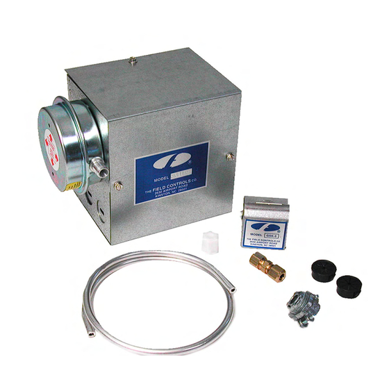
SYSTEM CONTROL KIT
Model: CK-41F
DO NOT DESTROY
THESE INSTRUCTIONS MUST REMAIN WITH EQUIPMENT
I
TEMS INCLUDED IN
1)
Junction box with mounted pressure
switch and post purge timer
1)
Fan control gas pressure switch
1)
2 ft. length of 1/4 inch aluminum tubing
2)
Flexible conduit connector
1)
GSK-3 Spillage switch
1)
1/4 inch tubing connector
2630 Airport Road · Kinston, NC 28504
Phone: 252-522-3031· Fax: 252-522-0214
www.fieldcontrols.com
K
:
IT
Advertisement
Table of Contents

Related Manuals for Field Controls 46335000


Summary of Contents for Field Controls 46335000
- Page 1 SYSTEM CONTROL KIT Model: CK-41F TEMS INCLUDED IN Junction box with mounted pressure switch and post purge timer Fan control gas pressure switch 2 ft. length of 1/4 inch aluminum tubing Flexible conduit connector GSK-3 Spillage switch 1/4 inch tubing connector Designed for use with the SWG Series Power Venter for controlling Natural Gas or L.P.
- Page 2 Figure 1 Figure 2 OUNTING UNCTION The junction box can be mounted at the venter or remotely mounted away from the venter. (See Figure 1 & Figure 2) NOTE: Make sure pressure switch is in a vertical position. The pressure switch will not sense properly in a horizontal position.
- Page 3 ROVING WITCH DJUSTMENTS After proper air flow is established, the pressure switch adjustment is made by turning the pressure switch adjustment screw clockwise (See Figure 4) until burner operation stops. Turn the adjustment screw counter clockwise until burner ignites. Turn the adjustment screw an additional ¼...
- Page 4 Diagram A – Typical Furnace Wiring Diagram B – Boiler Wiring with Aquastat Page 4...
- Page 5 Page 5...
- Page 6 Diagram E Page 6...
- Page 7 SYSTEM CONTROL CHECK OUT PROCEDURES 1. For furnaces or boilers, adjust the thermostat to call for heat and observe the power venting system for proper operation sequence. (Repeat if necessary) a. Thermostat calls for heat. b. Relay is energized and venter motor starts. c.
- Page 8 INSTALLATION INFORMATION CK-41F MODEL NO.:____________________________________________________________ INSTALLER'S NAME:_____________________________________________________ INSTALLER'S COMPANY: _________________________________________________ INSTALLER'S PHONE NO.: ________________________________________________ DATE OF INSTALLATION:_________________________________________________ P/N 46335000 Rev A 10/06 Page 8...
Need help?
Do you have a question about the 46335000 and is the answer not in the manual?
Questions and answers