Table of Contents
Advertisement
Quick Links
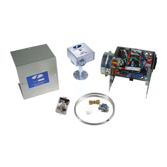
120 VAC SYSTEM CONTROL KIT
Designed for use on SWG Series Power Vent Hoods for controlling oil fi red
heating appliances with 120 VAC controls.
ITEMS INCLUDED IN KIT:
1- Junction box with mounted pressure switch and solid state post purge control
1- 2 Ft. Length of
1-
1
⁄
" tubing connector
4
1- Flexible conduit connector
1- WMO-1 Secondary Safety Switch
READ THESE INSTRUCTIONS CAREFULLY AND COMPLETELY BEFORE PROCEEDING WITH THE INSTALLATION.
This device MUST be installed by a qualifi ed agency in accordance with the manufacturer's installation instructions. The defi nition of
a qualifi ed agency is: any individual, fi rm, corporation or company which either in person or through a representative is engaged
in, and is responsible for, the installation and operation of HVAC appliances, who is experienced in such work, familiar with all the
precautions required, and has complied with all the requirements of the authority having jurisdiction.
Installed By:
Model: CK-61
1
⁄
" aluminum tubing
4
Please retain these instructions after installation.
Phone:
www.fi eldcontrols.com
Installation Date:
Advertisement
Table of Contents

Related Manuals for Field Controls CK-61


Summary of Contents for Field Controls CK-61
- Page 1 120 VAC SYSTEM CONTROL KIT Model: CK-61 Designed for use on SWG Series Power Vent Hoods for controlling oil fi red heating appliances with 120 VAC controls. ITEMS INCLUDED IN KIT: 1- Junction box with mounted pressure switch and solid state post purge control 1- 2 Ft.
- Page 2 1. Remove one of the knockouts from the side of the junction box where the pressure switch is mounted. Install the fl exible conduit connector onto the CK-61 junction box and secure with fastening nut. If remote mounting the CK-61 junction box, mount the fl exible conduit connector onto a 2”...
- Page 3 WIRING INSTRUCTIONS Wire the venter motor and controls in accordance with the National Electrical Code, manufacturer's recommendations and/or applicable local codes. UNIT MUST BE GROUNDED. Check ground circuit to make certain that the unit has been properly grounded. The wiring should be protected by an over current circuit device rated at 15 amperes.
- Page 4 Diagram C - Typical Wiring for Oil Fired WarmAir Furnace with a Honeywell ST9103 Control Board Diagram D - Riello Burner Application page 4...
- Page 5 Diagram E - Multiple Oil Fired Systems page 5...
- Page 6 ADJUSTMENTS PRESSURE SWITCH ADJUSTMENTS With the venter air fl ow set and the appliance operating at the best operating effi ciency, adjust the pressure switch by rotating the adjustment screw clockwise until the burner shuts off , then rotate the adjustment screw counterclockwise until the burner fi res.
- Page 7 SYSTEM CONTROL CHECK OUT PROCEDURES 1. Adjust the thermostat to call for heat and observe the power venting system for proper sequence of operation: (Repeat if necessary). a. Thermostat calls for heat. b. Relay is energized, post purge timer is energized, and venter motor starts. c.
- Page 8 WARRANTY For warranty about this or any Field Controls product, visit: www.fi eldcontrols.com/warranty Phone: 252.522.3031 • Fax: 252.522.0214 www.fieldcontrols.com © Field Controls, LLC P/N 46144900 Rev L 04/16...
Need help?
Do you have a question about the CK-61 and is the answer not in the manual?
Questions and answers