Table of Contents
Advertisement
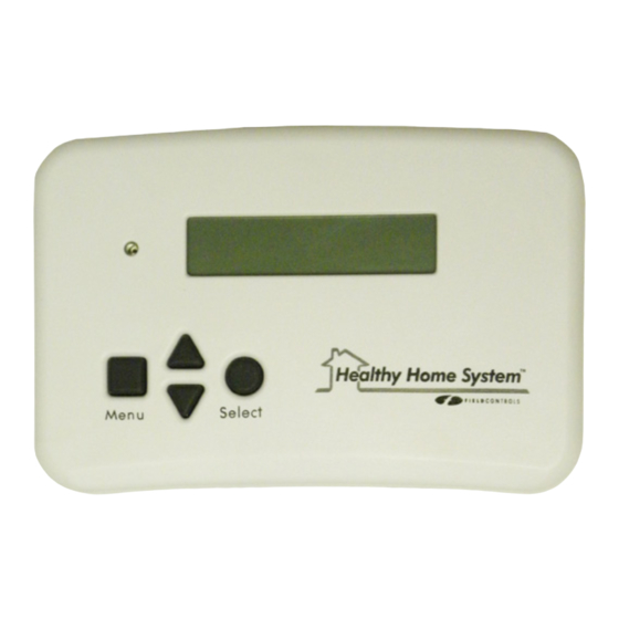
HEALTHY HOME SYSTEM
The Field Controls Healthy Home System™ Controller Plus (HHSC+) is designed to work in conjunction with
the forced air HVAC system to periodically introduce fresh air into the home by controlling an FAD Fresh Air
Damper installed in a fresh air duct connected to the HVAC return plenum, and circulate it throughout the
home effectively and efficiently, and enables the HVAC system to meet ASHRAE 62.2 and other ventilation
codes and standards.. The HHSC+ is designed to operate continuously year round without user intervention.
The HHSC+ is initially programed by the installer and operates interactively with the HVAC system thermostat.
Certain features are readily accessible by the occupants for customization of the system, to meet their individual
preferences.
ITEMS INCLUDED IN KIT:
1-HHSC+ Ventilation and Fan Cycling Control
1-Four-wire connector harness for FAD Fresh Air Damper (FAD not included)
1-Installation Hardware
1-Instruction Booklet
READ THESE INSTRUCTIONS CAREFULLY AND COMPLETELY BEFORE PROCEEDING WITH THE INSTALLATION.
This device MUST be installed by a qualified agency in accordance with the manufacturer's installation instructions. The definition of a
qualified agency is: any individual, firm, corporation or company which either in person or through a representative is engaged in, and
is responsible for, the installation and operation of HVAC appliances, who is experienced in such work, familiar with all the precautions
required, and has complied with all the requirements of the authority having jurisdiction.
Installed By:
CONTROL Plus
Model: HHSC+
Please retain these instructions after installation.
Phone:
www.fieldcontrols.com
Installation Date:
Advertisement
Table of Contents

Related Manuals for Field Controls HHSC+


Summary of Contents for Field Controls HHSC+
- Page 1 CONTROL Plus Model: HHSC+ The Field Controls Healthy Home System™ Controller Plus (HHSC+) is designed to work in conjunction with the forced air HVAC system to periodically introduce fresh air into the home by controlling an FAD Fresh Air Damper installed in a fresh air duct connected to the HVAC return plenum, and circulate it throughout the home effectively and efficiently, and enables the HVAC system to meet ASHRAE 62.2 and other ventilation...
- Page 2 FEATURES • System Status LED • User-Programmable Inhibit Mode • UV lamp replacement reminder • Air Filter replacement reminder • Time/Date display • Automatic Daylight Savings Time correction • Damper Monitor Feature monitors FAD damper for proper operation • Remote Activation Terminals: timer, on/off switch, Carbon Monoxide (CO) detector with alarm contacts, makeup air sensor, multiples having dry contacts •...
-
Page 3: Installation
INSTALLATION CHOOSE FAD FRESH AIR DAMPER LOCATION: The fresh air damper can be located anywhere in the fresh air inlet duct. Minimize the length of the inlet duct to improve airflow and improve system efficiency. It is recommended that the damper be as close to the return air plenum and the HHSC+ as possible, and that the inlet duct connect to the return plenum upstream of the system filter, and downstream of any duct-mounted sensors. -
Page 4: How To Install The Controller
INSTALLATION (con’t) HOW TO INSTALL DAMPER: The damper may be installed in any position; although it is recommended to install with the motor at the 3 or 9 o’clock position if mounted horizontally. Air may flow through in either direction, although it is recommended to install with the crimped end as the outlet of the damper. -
Page 5: Typical Wiring Diagrams
TYPICAL WIRING DIAGRAMS Figure 1 Single-Stage Heating/Cooling Figure 2 Multi-Stage Heating/Cooling page 5... - Page 6 TYPICAL WIRING DIAGRAMS (con’t) Figure 3 Heat Pump WIRING TO OPTIONAL EXHAUST FAN AND/OR OPTIONAL REMOTE OVERRIDE DEVICES Figure 4 Exhaust Fan & Override Device Control page 6...
- Page 7 OPTIONAL EXHAUST FAN CONTROL: The HHSC+ may optionally control an exhaust fan (not included) using the AUXC and AUXO auxiliary output terminals (wiring to thermostat and HVAC unit not shown for clarity) on the base. Connect the terminals to a 24 VAC relay (not included, 1A max. current) to control a 120 VAC exhaust fan. Whenever ventilation is occurring (the FAD damper is opened), these terminals will be energized and the fan relay will activate the exhaust fan to work in conjunction with the Healthy Home System to provide balanced ventilation.
-
Page 8: Navigating The Menu
SETUP NAVIGATING THE MENU Please refer to the color-coded Menu Map for guidance through the HHSC+ menu structure. Each colored box on the Map represents a particular menu item window that will appear on the HHSC+ display. The button colors, shapes, and action arrows in a Map item box correspond to the actions and settings available in the corresponding display menu item window. - Page 9 SETTING THE VENTILATION % TO MEET VENTILATION CODES: EXAMPLE: MEETING ASHRAE 62.2 2010 with given conditions: • 2000 square foot home (conditioned space) with 3 bedrooms • 140 cfm of fresh air flow as measured in the fresh air duct while system is operating Determine the required constant ventilation flow rate from table: 50 cfm. Measure the actual flow rate through the fresh air duct using a flow hood, anemometer, or Pitot tube and manometer, with the HVAC fan running on lowest speed and the FAD damper open (temporarily jumper AUX-IN to R terminal, or activate remote override device if connected): Example: 140 cfm measured.
- Page 10 CONTRACTOR SETUP MENU UV Lamp (R Replace UV Lamp Interval: UV Lamp + Filter Reset Timer 1YR, 2YR, NONE Timers > Ventilate: Ventilation Cycle Period Circulate: 30, 45, 60 MINUTES Parameters CONTRACTOR SETUP: PRESS for 5 sec. Damper Monitor: Damper Monitor: Testing Damper Disabled (Automatic)
- Page 11 Replace Filter Months: Filter: (Remaining) Days Remaining) Days 3, 6, 12, NONE Reset Timer ? NO (YES) NO (YES) MENU MAP 03/10/13 10:45AM 04/10/13 10:45AM 04/23/13 10:45AM 04/23/13 TES: SET MONTH: SET DAY: SET YEAR: System Inhibit 10:35PM duration: page 11...
- Page 12 Circulate % may be set equal to or greater than the Ventilate %, to cause the HVAC fan to run longer per cycle, for extra circulation, filtration, and UVC treatment if desired, or if the HHSC is used for circulation only.
- Page 13 HOMEOWNER (USER) SETTINGS The Homeowner Menu items (dark green Map item boxes) are directly available under normal operation, and are accessed simply by pressing the MENU button while at the home screen window, or from the Daylight Savings menu window in the Contractor Setup menu. It is not necessary to press MENU and SELECT to enter the Homeowner Settings menus.
-
Page 14: Independent Operation
SAVING THE SETUP While in the Menu = Continue/Select = Save & Exit window, press SELECT to save the setup settings, exit to the normal operation display window and begin normal operation, or MENU to continue with viewing the available menu items and settings. If no buttons are pushed for three minutes, any changes to settings will be automatically saved and the HHSC+ will return to normal operation with any changes to settings taking effect immediately. -
Page 15: Power Outage
ACTIVATION BY THERMOSTAT The HHSC+ monitors the activity of the thermostat and performs operations as described here. If the thermostat issues a demand for heating or cooling, or the HVAC fan is manually switched on, before an HHSC Fan On or Fan Cycle Period time expires (see Independent Operation above), the HHSC+ will immediately begin a new Fan Cycle period. - Page 16 OPERATION LED STATUS INDICATOR LIGHT A steady green light indicates that the Healthy Home System is operating properly. A steady red light indicates action should be taken; one or more messages will be displayed on the display, giving instructions for corrective action(s), such as HVAC filter life expiration, UV lamp life expiration, or a fault having been detected with the FAD damper (if enabled);...
-
Page 17: Replacement Parts
REPLACEMENT PARTS Pig Tail Harness P/N 46633900 Internal Battery Available at local retail outlets (See Battery Specification for replacement information) SPECIFICATIONS HHSC+ Electrical Wiring Requirements 18-22 AWG, 24 VAC min Operating Voltage 20-30 VAC Maximum Operating Current 1A per input/output circuit, 3A max. Combined Thermal Operating Ambient Temperature Range 32°F to 120°F (0°C to 49°C) - Page 18 page 18...
- Page 19 page 19...
- Page 20 Warranty For warranty information about this or any Field Controls product, visit: www.fieldcontrols.com/warranty Phone: 252.522.3031 • Fax: 252.522.0214 www.fieldcontrols.com © Field Controls, LLC P/N 46633800 Rev. A 07/15...
Need help?
Do you have a question about the HHSC+ and is the answer not in the manual?
Questions and answers