Table of Contents
Advertisement
Advertisement
Table of Contents

Related Manuals for Johnson Controls VB09


Summary of Contents for Johnson Controls VB09
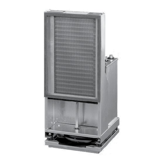
- Page 1 INDOOR PACKAGED EQUIPMENT Installation, Operation, and Maintenance Supersedes: 145.18-IOM1 (115) Form 145.18-IOM1 (818) HIGH EFFICIENCY VSCS SERIES VERTICAL STACKED WATER SOURCE HEAT PUMP LD27626 CABINET MODEL VB/VM/VS09–36 CHASSIS MODEL VSCS09–36 R-410A ISSUE DATE: August 30, 2018...
- Page 2 FORM 145.18-IOM1 ISSUE DATE: 8/30/2018 IMPORTANT! READ BEFORE PROCEEDING! GENERAL SAFETY GUIDELINES This equipment is a relatively complicated apparatus. which it is situated, as well as severe personal injury or During rigging, installation, operation, maintenance, death to themselves and others at the site. or service, individuals may be exposed to certain com- This document is intended for use by owner-authorized ponents or conditions including, but not limited to:...
- Page 3 FORM 145.18-IOM1 ISSUE DATE: 8/30/2018 CHANGEABILITY OF THIS DOCUMENT In complying with the manufacturer's’ policy for con- lifting, and operating/service personnel should verify tinuous product improvement, the information con- whether the equipment has been modified and if current tained in this document is subject to change without literature is available from the owner of the equipment notice.
- Page 4 FORM 145.18-IOM1 ISSUE DATE: 8/30/2018 CABINET NOMENCLATURE 1, 2 3, 4 10 11, 12 14 15 12 M D E A 2 PRODUCT CATEGORY DESIGN SERIES VB = Vertical Stacked Heat Pump - C = Current Generation Standard Cabinet Assembly VM = Vertical Stacked Heat Pump - Master Cabinet Assembly MISCELLANEOUS OPTIONS...
- Page 5 FORM 145.18-IOM1 ISSUE DATE: 8/30/2018 CHASSIS NOMENCLATURE 1, 2, 3, 4 5, 6 VSCS MISCELLANEOUS OPTIONS O = None PRODUCT CATEGORY VSCS = Vertical Stacked Heat Pump Chassis WATERSIDE OPTIONS R-410A C = Standard Water Coil B = Standard Water Coil with Low Temperature Option UNIT CAPACITY N = Cupro-Nickel Water Coil...
-
Page 6: Table Of Contents
FORM 145.18-IOM1 ISSUE DATE: 8/30/2018 TABLE OF CONTENTS SECTION 1 - INSTALLATION ..........................9 Notice and Disclaimer ............................9 Disclaimer ..............................9 Pre-Installation ..............................9 Literature ..............................9 Shipping ..............................9 Inspection and Storage .........................10 Preparations for Installing the Unit ......................10 Rigging ..............................11 Cabinet Riser Installation .......................... - Page 7 FORM 145.18-IOM1 ISSUE DATE: 8/30/2018 TABLE OF CONTENTS (CONT'D) SECTION 3 - MAINTENANCE ..........................43 APPENDIX ................................45 Heating and Cooling Data Record Sheet ....................... 49 R-410A Quick Reference Guide ........................51 LIST OF FIGURES FIGURE 1 - Ideal Riser Insertion Depth ........................12 FIGURE 2 - Correct/Incorrect Stub-Out Positions in Cabinet Riser Opening ............12 FIGURE 3 - Cabinet Unit Dimensions &...
- Page 8 FORM 145.18-IOM1 ISSUE DATE: 8/30/2018 LIST OF TABLES TABLE 1 - High Series Physical Data ........................13 TABLE 2 - Replacement Hose Gaskets ........................16 TABLE 3 - Chassis Hoses ............................16 TABLE 4 - Typical Wire Connections ........................19 TABLE 5 - Unit Supply Opening Sizes ........................26 TABLE 6 - Unit Supply Face Velocity (FPM) ......................26 TABLE 7 - Operating Limits ............................36 TABLE 8 - PSC Standard Blower Performance (CFM) ...................37...
-
Page 9: Section 1 - Installation
FORM 145.18-IOM1 ISSUE DATE: 8/30/2018 SECTION 1 - INSTALLATION After installing the unit, show the user Modifications may invalidate product certifications or how to turn off the electricity to the unit. violate country standards. Any person or entity making Point out control and switch locations for changes to the product is responsible for obtaining the turning off the electricity. -
Page 10: Inspection And Storage
FORM 145.18-IOM1 SECTION 1 - INSTALLATION ISSUE DATE: 8/30/2018 Inspection and Storage • Remove the inner service panel and manually check the blower wheel for free rotation. Store cabinets, chassis, and risers the same way they were shipped. Ensure the storage area is dry and pro- •... -
Page 11: Rigging
FORM 145.18-IOM1 SECTION 1 - INSTALLATION ISSUE DATE: 8/30/2018 Safety guards, shields, barriers, cov- CABINET RISER INSTALLATION ers, and protective devices must not be Do NOT use the risers to lift or move the removed while the compressor/unit is cabinets. operating. -
Page 12: Figure 1 - Ideal Riser Insertion Depth
FORM 145.18-IOM1 SECTION 1 - INSTALLATION ISSUE DATE: 8/30/2018 1. Place the cabinet in a horizontal position on the 7. Center the risers’ horizontal stub-outs (complete floor adjacent to its installation location (when ris- with factory-installed shut-off valves) in the cabi- ers are attached to cabinet). -
Page 13: Table 1 - High Series Physical Data
FORM 145.18-IOM1 SECTION 1 - INSTALLATION ISSUE DATE: 8/30/2018 10. Braze or solder riser joints with industry accepted 11. Secure the riser system at a minimum of one point solder or brazing rod material. to the building structure. Cabinets are not intend- ed to support the riser system. -
Page 14: Figure 3 - Cabinet Unit Dimensions & Floor Sleeve Dimensions
FORM 145.18-IOM1 SECTION 1 - INSTALLATION ISSUE DATE: 8/30/2018 CABINET DIMENSIONS (INCHES) RA FLANGE MODEL Optional WIDTH (C) Front Supply Optional 24V 09–18 Opening Connection for Surface Mount/ 15–24 7/8-inch 7 inches Remote Mounted Control 30–36 Thermostat Entrance Switch Plate with 2 Speed Fan Electrical Box Switch (Optional:... -
Page 15: Figure 4 - Cabinet Riser Dimensions
FORM 145.18-IOM1 SECTION 1 - INSTALLATION ISSUE DATE: 8/30/2018 Allow for 2-inch Insertion 3 in. into Swage End Insulation Optional Supply Opening Shut-Off Return Air Ball Valve Supply Opening Return Risers 6 in. P-Trap Reducer Reducer NOTE Riser shut-off valve is measured from base of cabinet and does not include the stand height. LD19330 FIGURE 4 - CABINET RISER DIMENSIONS... -
Page 16: Riser Loop
FORM 145.18-IOM1 SECTION 1 - INSTALLATION ISSUE DATE: 8/30/2018 RISER LOOP HOSES 5. Install the following parts at the base of each sup- Ensure the correct hose set is matched with the com- ply and return riser to enable system flushing, bal- patible unit size (see Table 3). -
Page 17: Figure 5 - Standard Factory Supplied Npsh Hose Kits And Risers
FORM 145.18-IOM1 SECTION 1 - INSTALLATION ISSUE DATE: 8/30/2018 1/2-INCH OR 3/4-INCH MALE NPSH BALL VALVE 1/2-INCH OR 3/4-INCH NPSH THREADS 1/2-INCH OR 3/4-INCH FLEXIBLE CONNECTOR HOSE (24 INCHES LONG) GASKET GASKET 1/2-INCH OR 3/4-INCH NPSH THREADS 1/2-INCH OR 3/4-INCH MALE NPSH NOTE National Pipe Straight Hose (NPSH) connection LD18126... -
Page 18: Electrical Wiring
FORM 145.18-IOM1 SECTION 1 - INSTALLATION ISSUE DATE: 8/30/2018 1/2-INCH OR 3/4-INCH FPT BALL VALVE (FACTORY OR FIELD PROVIDED) FEMALE SWIVEL 1/2-INCH OR 3/4-INCH NPSH THREADS 1/2-INCH OR 3/4-INCH FLEXIBLE CONNECTOR HOSE (24 INCHES LONG) GASKET INCLUDED WITH HOSE ADAPTER MPT TO NPSH INCLUDED WITH HOSE FEMALE SWIVEL 1/2-INCH OR 3/4-INCH NPSH THREADS... -
Page 19: Optional Surface Mount Thermostat Connection Wiring
FORM 145.18-IOM1 SECTION 1 - INSTALLATION ISSUE DATE: 8/30/2018 Install the thermostat by connecting the remote ther- Optional Surface Mount Thermostat mostat wiring to microprocessor board low voltage Connection Wiring terminal strip. See Figure 8 for typical wiring connec- For applications where the thermostat is mounted di- tions. -
Page 20: Optional Ada Door Mounted Thermostat
FORM 145.18-IOM1 SECTION 1 - INSTALLATION ISSUE DATE: 8/30/2018 CLOSET AND DRYWALL INSTALLATION To avoid potential vibration and noise is- sues, the RA panel should not contact any Optional Disconnect part of the unit cabinet or sleeve. Maintain a sufficient gap between RA panel frame and cabinet. -
Page 21: Figure 11 - Critical Return Air (Ra) Panel With Unit Cabinet Installation Dimensions
FORM 145.18-IOM1 SECTION 1 - INSTALLATION ISSUE DATE: 8/30/2018 1. Locate the drywall opening at a distance from Figure 14 on page 23 shows the opening for mount- the unit so that it prevents the RA panel from ing an ADA compliant thermostat at 48 inches above contacting the unit sleeve. -
Page 22: Figure 12 - Ra Panel Cross Section Installation At Floor Level
FORM 145.18-IOM1 SECTION 1 - INSTALLATION ISSUE DATE: 8/30/2018 Figure 12 on page 22 shows a cutaway view for a RA flange must not standard cabinet with no stand. Add the stand height to contact door frame the cabinet to obtain the correct dimension of the RA panel from floor. -
Page 23: Figure 14 - Optional Ra Panel With Ada Mounted Thermostat
FORM 145.18-IOM1 SECTION 1 - INSTALLATION ISSUE DATE: 8/30/2018 Left Hand Opening Shown LEFT HAND OPENING SHOWN 1.50 1.5 inches 1.25 1.25 inches Thermostat mounting location, Thermostat mounting location, Cut-out for routing cut-out for routing ADA thermostat ADA thermostat harness 1/2"... -
Page 24: Supply Air (Sa) Ductwork
FORM 145.18-IOM1 SECTION 1 - INSTALLATION ISSUE DATE: 8/30/2018 SUPPLY AIR (SA) DUCTWORK Top Discharge Supply Air Ensure there is no direct contact between Units that are installed with a top discharge should be cabinet sheet metal parts and drywall en- connected to the supply ductwork with a watertight closure. -
Page 25: Figure 16 - Unit Mounted Supply Grille Installation
FORM 145.18-IOM1 SECTION 1 - INSTALLATION ISSUE DATE: 8/30/2018 VERTICAL STACK CABINET Vertical Stack Cabinet Wall Stud WALL STUD Top View TOP VIEW Detail A DETAIL A Optional Opposed Blade Damper Louvered Supply Grille 0.5-inch Drywall 1/2” 1/8” THICK FIELD SUPPLIED 1/8-inch Thick Field Supplied DRYWALL GASKET TAPE... -
Page 26: Table 5 - Unit Supply Opening Sizes
FORM 145.18-IOM1 SECTION 1 - INSTALLATION ISSUE DATE: 8/30/2018 TABLE 5 - UNIT SUPPLY OPENING SIZES HORIZONTAL OPENINGS TRIPLE SINGLE HORIZONTAL DOUBLE HORIZONTAL HORIZONTAL TOP OPENING NO TOP NO TOP NO TOP MODEL TOP OPENING TOP OPENING OPENING OPENING OPENING 14W x 12H 14W x 6H 14W x 8H... -
Page 27: Top Mounted Fresh Air Intake
FORM 145.18-IOM1 SECTION 1 - INSTALLATION ISSUE DATE: 8/30/2018 During transportation, handling or instal- TOP MOUNTED FRESH AIR INTAKE lation of the cabinet, excessive handling The optional fresh air intake provides a 4-inch round can cause an inner black plastic cover to duct connection on top of the unit (see Figure 23 on come loose and jam the actuator, prevent- page 31 for right and left hand version). -
Page 28: System Flushing And Cleaning
FORM 145.18-IOM1 SECTION 1 - INSTALLATION ISSUE DATE: 8/30/2018 SYSTEM FLUSHING AND CLEANING After the piping system is complete, and before con- necting the refrigeration chassis, flush and clean the risers This ensures a proper start-up and continued ef- ficient operation of the system (see Figure 20 on page 29). -
Page 29: Cleaning The System
FORM 145.18-IOM1 SECTION 1 - INSTALLATION ISSUE DATE: 8/30/2018 10. Continue to bleed the system until the water leav- Hose or piping Hose or piping connecting ing the drain is clear, no less than 2 hours. connecting supply supply & return runouts and return runouts 11. -
Page 30: Figure 21 - Fresh Air Opening Without Motorized Damper - Left And Right Hand Unit Shown
FORM 145.18-IOM1 SECTION 1 - INSTALLATION ISSUE DATE: 8/30/2018 CABINET DIMENSIONS (INCHES) MODEL Front Supply Flange 09–12 (Optional) 15–24 30–36 Fresh Air Discharge Collector Box 1. Optional fresh air option comes with 2.5-inch RA flange. 2. Optional front supply opening comes with 2.5-inch duct flange. 3. -
Page 31: Figure 22 - Fresh Air Opening With Motorized Damper - Left And Right Hand Unit Shown
FORM 145.18-IOM1 SECTION 1 - INSTALLATION ISSUE DATE: 8/30/2018 4-inch Ø Fresh Air Take-Off Intake CABINET DIMENSIONS (INCHES) MODEL 09–12 15–24 Optional Front Supply 30–36 (4.25-inch Flange) 1. Optional fresh air option comes with 4.25-inch RA flange. 2. Optional front supply opening comes with 4.25-inch duct flange. Fresh Air Discharge 3. -
Page 32: Chassis Installation
FORM 145.18-IOM1 SECTION 1 - INSTALLATION ISSUE DATE: 8/30/2018 CHASSIS INSTALLATION Remove the inner service panel from the cabinet, and inspect the interior compartment for debris. Clear all Prior to installation of the refrigeration debris and vacuum construction dust from the cabinet. chassis and connection to the supply and return risers, the entire water loop system Locate the supply and return shut-off valves. -
Page 33: Figure 23 - Lift The Chassis Front
FORM 145.18-IOM1 SECTION 1 - INSTALLATION ISSUE DATE: 8/30/2018 1. Thread the swivel adapters into the female pipe thread fittings projecting through the top of the compressor compartment access cover. To prevent twisting of the copper water piping in the chassis assembly, always use a backup wrench. -
Page 34: Figure 26 - Pivot The Chassis
FORM 145.18-IOM1 SECTION 1 - INSTALLATION ISSUE DATE: 8/30/2018 Do not apply excessive force when sliding chassis into cabinet. 6. Slide the chassis into the cabinet until at least 3/4 of the depth of the chassis is supported. The chas- sis should slide easily on the drain pan rails. -
Page 35: Section 2 - Operation
FORM 145.18-IOM1 ISSUE DATE: 8/30/2018 SECTION 2 - OPERATION INITIAL UNIT START-UP Once the installation is complete and the system is During installation, testing, servicing, cleaned and flushed, begin unit start-up. Open the sup- and troubleshooting of this product, it ply and return shut-off valves at each unit, refill the may be necessary to work with live electri- system, and bleed off all air. -
Page 36: System Loop Temperature
FORM 145.18-IOM1 SECTION 2 - OPERATION ISSUE DATE: 8/30/2018 • The blower and compressor operation are FAN SPEED ADJUSTMENT smooth with no frost observed in the refrig- Multi-speed direct drive motors are used in all units as erant circuit. standard. Permanent split capacitor (PSC) fan motors 10. -
Page 37: Table 8 - Psc Standard Blower Performance (Cfm)
FORM 145.18-IOM1 SECTION 2 - OPERATION ISSUE DATE: 8/30/2018... -
Page 38: Table 10 - Ecm Standard Blower Performance (Cfm)
FORM 145.18-IOM1 SECTION 2 - OPERATION ISSUE DATE: 8/30/2018... -
Page 39: Table 12 - Ecm Blower Performance - All Speed Taps (Cfm)
FORM 145.18-IOM1 SECTION 2 - OPERATION ISSUE DATE: 8/30/2018... -
Page 40: Unit Controls
FORM 145.18-IOM1 SECTION 2 - OPERATION ISSUE DATE: 8/30/2018 UNIT CONTROLS If at any time there is a call for both heating and cool- ing, the heating operation is performed. Heating always The control system microprocessor board is specifi- takes priority. If cooling mode is operating, it halts and cally designed for water source heat pump operation. -
Page 41: Operation Errors
FORM 145.18-IOM1 SECTION 2 - OPERATION ISSUE DATE: 8/30/2018 If the unit must be reset more than twice If a low pressure limit switch opens three times within 1 hour of operation, the microprocessor control board on consecutive operating cycles, check locks out the compressor (a hard lockout) and flashes a the unit for a dirty filter, abnormal EWT, fault code (see Table 13 on page 42). -
Page 42: Random Start
FORM 145.18-IOM1 SECTION 2 - OPERATION ISSUE DATE: 8/30/2018 Installing the jumper bypasses the freeze-stat, enabling Last Error heating operation with a leaving glycol fluid mixture When this button is pressed and released one time temperature below 35.0°F. Use the jumper only in low within 5 seconds, it flashes the last five fault codes on water applications with adequate antifreeze protection, the board’s LED. -
Page 43: Section 3 - Maintenance
FORM 145.18-IOM1 ISSUE DATE: 8/30/2018 SECTION 3 - MAINTENANCE Unit maintenance is simplified by the following pre- 4. Annually check the fan motor and blower assem- ventive suggestions: bly. All units employ permanently lubricated fan motors. DO NOT OIL FAN MOTORS. Vacuum 1. - Page 44 FORM 145.18-IOM1 SECTION 3 - MAINTENANCE ISSUE DATE: 8/30/2018 THIS PAGE INTENTIONALLY LEFT BLANK.
-
Page 45: Appendix
FORM 145.18-IOM1 ISSUE DATE: 8/30/2018 APPENDIX LD23571 FIGURE 29 - PSC MOTOR WIRING DIAGRAM... -
Page 46: Figure 30 - Ecm Wiring Diagram
FORM 145.18-IOM1 APPENDIX ISSUE DATE: 8/30/2018 LD23572 FIGURE 30 - ECM WIRING DIAGRAM... -
Page 47: Figure 31 - Continuous Fan With Ecm Wiring Diagram
FORM 145.18-IOM1 APPENDIX ISSUE DATE: 8/30/2018 LD27633 FIGURE 31 - CONTINUOUS FAN WITH ECM WIRING DIAGRAM... -
Page 48: Figure 32 - Motorized Damper Ecm Wiring Diagram
FORM 145.18-IOM1 APPENDIX ISSUE DATE: 8/30/2018 LD23574 FIGURE 32 - MOTORIZED DAMPER ECM WIRING DIAGRAM... -
Page 49: Heating And Cooling Data Record Sheet
INDOOR PACKAGED EQUIPMENT FORM 145.18-IOM1 APPENDIX ISSUE DATE: 8/30/2018 VERTICAL STACKED WATER SOURCE HEAT PUMP HEATING AND COOLING DATA RECORD SHEET HEATING AND COOLING DATA RECORD SHEET JOB NAME: _____________________________________ JOB #: _________________________________________ JOB ADDRESS: _________________________________ DATE: _________________________________________ _______________________________________________ INSTALLER'S ADDRESS: _________________________ INSTALLER: ____________________________________ _______________________________________________ SPECIAL QUOTES/OPTIONS (YES/NO): _____________... - Page 50 FORM 145.18-IOM1 APPENDIX ISSUE DATE: 8/30/2018 °F Air Coil psi = SAT °F Compressor Reversing Valve Airflow Airflow Suction Coil Inlet (Dry Bulb) °F Coaxial Coil Outlet (Dry Bulb) °F Coil Coil Inlet (Wet Bulb) °F Coil Outlet (Wet Bulb) °F Air Relative Humidity (%) °F...
-
Page 51: R-410A Quick Reference Guide
FORM 145.18-IOM1 ISSUE DATE: 8/30/2018 R-410A QUICK REFERENCE GUIDE • Systems must be charged with refrigerant. Use a commercial type metering device in the manifold See Section 1 - Installation for specific installation re- hose. quirements. • R-410A refrigerant can only be used with polyes- •... - Page 52 100 JCI Way, York, Pennsylvania USA 17406-8469 800-861-1001 Subject to change without notice. Printed in USA Copyright © by Johnson Controls 2018 www.johnsoncontrols.com ALL RIGHTS RESERVED Form 145.18-IOM1 (818) Issue Date: August 30, 2018 Supersedes: 145.18-IOM1 (115)
Need help?
Do you have a question about the VB09 and is the answer not in the manual?
Questions and answers