Table of Contents
Advertisement
INSTALLATION
MANUAL
CONTENTS
GENERAL . . . . . . . . . . . . . . . . . . . . . . . . . . . . . . . . . . . .3
INSPECTION . . . . . . . . . . . . . . . . . . . . . . . . . . . . . . . . . .3
REFERENCE . . . . . . . . . . . . . . . . . . . . . . . . . . . . . . . . . .3
REPLACEMENT PARTS . . . . . . . . . . . . . . . . . . . . . . . . .3
PRODUCT NOMENCLATURE . . . . . . . . . . . . . . . . . . . .3
INSTALLATION . . . . . . . . . . . . . . . . . . . . . . . . . . . . . . . .4
SEQUENCE OF OPERATION . . . . . . . . . . . . . . . . . . . .13
MAINTENANCE . . . . . . . . . . . . . . . . . . . . . . . . . . . . . . .15
See the following page for a complete Table of Contents.
NOTES, CAUTIONS AND WARNINGS
Installer should pay particular attention to the words:
NOTE, CAUTION, and WARNING. Notes are
intended to clarify or make the installation easier.
Cautions are given to prevent equipment damage.
Warnings are given to alert installer that personal
injury and/or equipment damage may result if instal-
lation procedure is not handled properly.
CAUTION: READ ALL SAFETY GUIDES BEFORE
YOU BEGIN TO INSTALL YOUR UNIT.
SAVE THIS MANUAL
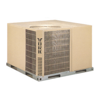
AFFINITY™ SERIES
SINGLE PACKAGE HEAT PUMPS
MODEL: B1HA036 thru 060
3 thru 5 Ton
(10 SEER)
SO 9001
Certified Quality
Management System
341849-YIM-A-0108
Advertisement
Table of Contents

Subscribe to Our Youtube Channel
Related Manuals for Johnson Controls B1HA036


Summary of Contents for Johnson Controls B1HA036
- Page 1 CONTENTS MODEL: B1HA036 thru 060 GENERAL ........3 3 thru 5 Ton INSPECTION .
-
Page 2: Table Of Contents
COOLING SUPERHEAT AT COMPRESSOR SUCTION, AIRFLOW = 1,200 CFM (B1HA036) ....10 HEATING OPERATION ..... . 13 DEFROST OPERATION . -
Page 3: General
NOMINAL COOLING INSTALLED ELECTRIC HEAT CAPACITY (MBH) A = No Electric Heat Installed PRODUCT IDENTIFIER 036 = 36,000 BTUH 042 = 42,000 BTUH HA = Heat Pump (10 SEER) 048 = 48,000 BTUH 060 = 60,000 BTUH Johnson Controls Unitary Products... -
Page 4: Installation
Do not tie the slab to the building foundation. Do not permit overhanging structures or shrubs 4. For roof top installation, be sure the structure will to obstruct the condenser air discharge outlets. support the weight of the unit plus any field Johnson Controls Unitary Products... -
Page 5: Ductwork
Refer to Figure 2 for typical field wiring and to the appropriate unit wiring diagram for control circuit and Filters should be checked monthly especially since this power wiring information. unit is used for both heating and cooling. Johnson Controls Unitary Products... -
Page 6: Compressors
Outdoor Fins Per Inch Coil Face Area (Sq. Ft.) 11.7 11.7 16.4 16.4 Charge Refrigerant 22 (Lbs./oz.) 10/0 Filter Face Area (Sq. Ft./qty./size) 4.28/2/14" x 22" Compressor Hermetic Type, (Qty. = 1) Scroll Recip. Scroll Scroll Johnson Controls Unitary Products... -
Page 7: Electrical Data
460-3-60 40.0 460-3-60 42.0 460-3-60 55.0 11.7 460-3-60 67.0 14.3 575-3-60 32.0 575-3-60 44.0 575-3-60 44.0 575-3-60 50.0 11.4 1. Rated in accordance with ARI Standard 110, utilization range “A”. 2. Dual element, time delay type. Johnson Controls Unitary Products... -
Page 8: Side & Bottom Supply Air Blower Performance 230/460/575 Volts
2. The pressure thru the economizer is greater for 100% outdoor air than for 100% return air. If the resistance of the return air duct system is less than 0.25 IWG, the unit will deliver less CFM during full economizer operation. Johnson Controls Unitary Products... -
Page 9: Checking Supply Air Cfm
B1HA Coil Delta B1HA036 B1HA048-60 B1HA042 Linear B1HA036 Linear B1HA042 Linear B1HA048-60 Airflow (CFM) FIGURE 3 - Coil Delta P vs. Supply Air CFM Johnson Controls Unitary Products... -
Page 10: Cooling Superheat At Compressor Suction, Airflow = 1,200 Cfm (B1Ha036)
341849-YIM-A-0108 TABLE 9: Cooling Superheat at Compressor Suction, Airflow = 1,200 CFM (B1HA036) Outdoor Indoor WB Temperature, °F Temperature °F 12.8 16.1 19.3 22.5 25.8 29.0 32.2 35.0 37.7 40.4 43.1 11.4 14.3 17.2 20.1 22.9 25.8 28.7 31.6 34.4 37.3... -
Page 11: Cooling Superheat At Compressor Suction, Airflow = 1,600 Cfm (B1Ha048)
15.3 18.2 21.1 11.2 13.4 15.6 17.8 10.0 11.5 13.0 14.4 10.3 11.1 TABLE 16: Heating Superheat at Compressor Suction, Airflow = 2,000 CFM (B1HA060) Indoor DB Outdoor Temperature, °F Temperature °F 13.1 18.6 13.4 11.0 Johnson Controls Unitary Products... -
Page 12: Dimensions And Clearances
1. Units may be installed on combustible floors made from wood or class A, B or C roof covering material. 2. Units must be installed outdoors. Overhanging structures or shrubs should not obstruct outdoor air discharge outlet. FIGURE 4 - Dimensions and Clearances Johnson Controls Unitary Products... -
Page 13: Sequence Of Operation
If the fan for 5 seconds. Defrost will terminate normally during switch on the thermostat is in the “AUTO” position, the “TEST” mode. the blower will operate only when there is a call for heating by the thermostat. Johnson Controls Unitary Products... -
Page 14: Heat Pump Safety Switch Operation
HEATER BANK 4, 5 & 6 ELEC. HEAT 10 SEC. DELAY ON “W” HEATER BANK 4, 5 & 6 ELEC. HEAT INSTANT OFF HEATER BANK 1, 2 & 3 ELEC. HEAT 1/2 SEC. DELAY OFF FAN 10 SEC. DELAY OFF Johnson Controls Unitary Products... -
Page 15: Maintenance
Permanent Type as necessary. DO NOT to be obstructed by overhanging structures or replace Permanent Type with Disposable. shrubs. MOTORS - Indoor and outdoor fan motors are perma- nently lubricated and require no maintenance. Johnson Controls Unitary Products... -
Page 16: Typical Wiring Diagram (230-3-60 Power Supply)
341849-YIM-A-0108 DETAIL A COMPR RELAY 222/Y DFST STAT FOR DEFROST CONTROL 031-09104-000A DEFROST CONTROL SEE DETAIL A 031-01268-000B FIGURE 5 - Typical Wiring Diagram (230-3-60 Power Supply) Johnson Controls Unitary Products... -
Page 17: Typical Wiring Diagram Bha Models (460-3-60 And 575-3-60 Power Supply)
341849-YIM-A-0108 FIGURE 6 - Typical Wiring Diagram BHA Models (460-3-60 and 575-3-60 Power Supply) Johnson Controls Unitary Products... -
Page 18: Typical Wiring Diagram Legend
WIRE 204/BR IS REMOVED WHEN ELECTRIC HEAT IS INSTALLED. ELECTRIC HEAT ACCESSORY WITH DUAL POINT SUPPLY POWER. SEE DETAIL A 10. SHUNT CONTACT ALSO USED WITH CRANKCASE HEATER. (OPTIONAL) FIGURE 8 - Typical Wiring Diagram Notes (See Pages 16 and 17) Johnson Controls Unitary Products... - Page 19 341849-YIM-A-0108 Johnson Controls Unitary Products...
- Page 20 Subject to change without notice. Printed in U.S.A. 341849-YIM-A-0108 Copyright © 2007 by Johnson Controls, Inc. All rights reserved. Supersedes: 66269-YIM-A-0104/035-16004-002-A-0104 Johnson Controls Unitary Products 5005 York Drive Norman, OK 73069...
Need help?
Do you have a question about the B1HA036 and is the answer not in the manual?
Questions and answers