Sign In
Upload
Manuals
Brands
Johnson Controls Manuals
Heat Pump
VB09
Johnson Controls VB09 Manuals
Manuals and User Guides for Johnson Controls VB09. We have
1
Johnson Controls VB09 manual available for free PDF download: Installation, Operation And Maintenance Manual
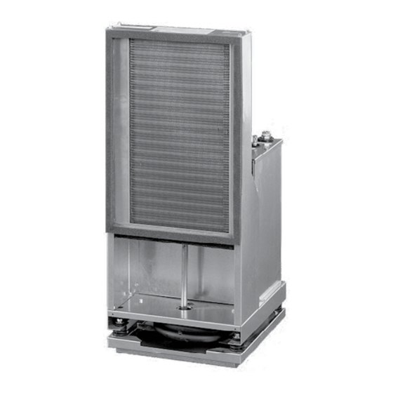
Johnson Controls VB09 Installation, Operation And Maintenance Manual (52 pages)
HIGH EFFICIENCY VSCS SERIES VERTICAL STACKED WATER SOURCE HEAT PUMP R-410A
Brand:
Johnson Controls
| Category:
Heat Pump
| Size: 5 MB
Table of Contents
Table of Contents
6
Section 1 - Installation
9
Notice and Disclaimer
9
Disclaimer
9
Pre-Installation
9
Literature
9
Shipping
9
Inspection and Storage
10
Preparations for Installing the Unit
10
Rigging
11
Cabinet Riser Installation
11
Placing the Cabinet
11
FIGURE 2 - Correct/Incorrect Stub-Out Positions in Cabinet Riser Opening
12
TABLE 2 - Replacement Hose Gaskets
16
TABLE 3 - Chassis Hoses
16
FIGURE 5 - Standard Factory Supplied NPSH Hose Kits and Risers
17
FIGURE 6 - Optional Field Supplied Risers with Factory Supplied NPSH Hose Kits and Shut-Off Valves
17
FIGURE 7 - Conversion of NPT to NPSH Type Fittings (VB Units with NPT Fittings Only)
18
FIGURE 8 - Field Wiring Diagram
19
FIGURE 9 - Remote Thermostat Wiring
19
Optional Remote Mounted Thermostat Wiring
19
Optional Surface Mount Thermostat Connection Wiring
19
TABLE 4 - Typical Wire Connections
19
Acoustic Return Air (RA) Panel
20
Closet and Drywall Installation
20
EC Motor (ECM) Continuous Fan
20
FIGURE 10 - Unit Switch Plate with ADA Thermostat Connection
20
Optional ADA Door Mounted Thermostat
20
FIGURE 11 - Critical Return Air (RA) Panel with Unit Cabinet Installation Dimensions
21
FIGURE 12 - RA Panel Cross Section Installation at Floor Level
22
FIGURE 13 - RA Panel Dimensions
22
FIGURE 14 - Optional RA Panel with ADA Mounted Thermostat
23
FIGURE 15 - Supply Grille with Volume Damper and 1/8-Inch Neoprene Tape Applied to Perimeter
24
Horizontal Supply Air
24
Supply Air (SA) Ductwork
24
Top Discharge Supply Air
24
FIGURE 16 - Unit Mounted Supply Grille Installation
25
TABLE 5 - Unit Supply Opening Sizes
26
TABLE 6 - Unit Supply Face Velocity (FPM)
26
FIGURE 17 - Damper Plate Fasteners
27
FIGURE 18 - Remove the Red Cover
27
Top Mounted Fresh Air Intake
27
Top Mounted Fresh Air Intake with Motorized Damper
27
FIGURE 19 - Position Black Cover
28
Flushing the System
28
System Flushing and Cleaning
28
Cleaning the System
29
FIGURE 20 - System Flushing and Cleaning
29
FIGURE 21 - Fresh Air Opening Without Motorized Damper - Left and Right Hand Unit Shown
30
FIGURE 22 - Fresh Air Opening with Motorized Damper - Left and Right Hand Unit Shown
31
Chassis Installation
32
For Units with NPSH Valve Connection and Hose Sets
32
For Units with NPT Style (Tapered Pipe Thread) Valve Connection and Hoses
32
Electrical Wiring
18
Field-Installed Low Voltage Wiring
18
Field-Installed Power Wiring
18
FIGURE 1 - Ideal Riser Insertion Depth
12
TABLE 1 - High Series Physical Data
13
FIGURE 3 - Cabinet Unit Dimensions & Floor Sleeve Dimensions
14
FIGURE 4 - Cabinet Riser Dimensions
15
Hoses
16
Riser Loop
16
FIGURE 23 - Lift the Chassis Front
33
FIGURE 24 - Tilt the Chassis
33
FIGURE 25 - Insert the Chassis
33
FIGURE 26 - Pivot the Chassis
34
FIGURE 27 - Slide the Chassis
34
FIGURE 28 - Check the Chassis
34
Section 2 - Operation
35
Initial Unit Start-Up
35
Pre-Start-Up Checklist
35
Fan Speed Adjustment
36
System Loop Temperature
36
TABLE 7 - Operating Limits
36
TABLE 8 - PSC Standard Blower Performance (CFM)
37
TABLE 9 - PSC High Static Blower Performance (CFM)
37
TABLE 10 - ECM Standard Blower Performance (CFM)
38
TABLE 11 - ECM High Static Blower Performance (CFM)
38
TABLE 12 - ECM Blower Performance - All Speed Taps (CFM)
39
Unit Controls
40
Sequence of Operation
40
Continuous Blower
40
Safety Control Reset
40
Operation Errors
41
Safety Controls
41
Random Start
42
Compressor Protection
42
Microprocessor Control Unit Flash Codes
42
Communication
42
TABLE 13 - Flash Codes
42
Section 3 - Maintenance
43
Appendix
45
FIGURE 29 - PSC Motor Wiring Diagram
45
FIGURE 30 - ECM Wiring Diagram
46
FIGURE 31 - Continuous Fan with ECM Wiring Diagram
47
FIGURE 32 - Motorized Damper ECM Wiring Diagram
48
Heating and Cooling Data Record Sheet
49
R-410A Quick Reference Guide
51
Advertisement
Advertisement
Related Products
Johnson Controls VB12
Johnson Controls VB15
Johnson Controls VB18
Johnson Controls VB30
Johnson Controls VB24
Johnson Controls VB36
Johnson Controls VBR09 Series
Johnson Controls VBR15 Series
Johnson Controls VBR18 Series
Johnson Controls VBR24 Series
Johnson Controls Categories
Controller
Air Conditioner
Thermostat
Control Unit
Irrigation System
More Johnson Controls Manuals
Login
Sign In
OR
Sign in with Facebook
Sign in with Google
Upload manual
Upload from disk
Upload from URL