Table of Contents
Troubleshooting

Related Manuals for Johnson Controls HMH7 Series


Summary of Contents for Johnson Controls HMH7 Series
- Page 1 Installation Manual: HMH7 Series - 17 SEER Horizontal Discharge Modulating Heat Pump York International Corporation, 5005 York 6046972-UIM-A-0221 Drive, Norman, OK 73069 Supersedes: Nothing 2021-02-03 Johnson Controls Ducted Systems...
- Page 2 Installation Manual: HMH7 Series - 17 SEER Horizontal Discharge Modulating Heat Pump Johnson Controls Ducted Systems...
-
Page 3: Table Of Contents
Running a parameter query......... 29 Oil trap................30 Control mode..............31 Sensor parameter............31 Troubleshooting..............32 Checking components........... 32 Fault codes..............35 Troubleshooting guide..........46 Start-up sheet............... 49 Installation Manual: HMH7 Series - 17 SEER Horizontal Discharge Modulating Heat Pump Johnson Controls Ducted Systems... - Page 4 Installation Manual: HMH7 Series - 17 SEER Horizontal Discharge Modulating Heat Pump Johnson Controls Ducted Systems...
-
Page 5: General
• Leak detectors must be designed to detect HFC refrigerant. • Recovery equipment (including refrigerant recovery containers) must be specifically designed to handle R-410A. Installation Manual: HMH7 Series - 17 SEER Horizontal Discharge Modulating Heat Pump Johnson Controls Ducted Systems... -
Page 6: Limitations
(g/m) HMH72B24 164 (50) 98 (30) 0.38 (11) HMH72B36 246 (75) 98 (30) 0.38 (11) HMH72B48, 246 (75) 98 (30) 0.60 (17) HMH72B60 Installation Manual: HMH7 Series - 17 SEER Horizontal Discharge Modulating Heat Pump Johnson Controls Ducted Systems... - Page 7 Never install a suction-line filter drier in the liquid line of an R-410A system. Failure to follow this warning can cause a fire, injury, or death. Installation Manual: HMH7 Series - 17 SEER Horizontal Discharge Modulating Heat Pump Johnson Controls Ducted Systems...
-
Page 8: Unit Installation
Installation Manual: HMH7 Series - 17 SEER Horizontal Discharge Modulating Heat Pump Johnson Controls Ducted Systems... -
Page 9: Installing The Drain Elbow And Drain Hose
• To prevent exposure to wind, install a baffle board on the air outlet side of the outdoor unit. Installation Manual: HMH7 Series - 17 SEER Horizontal Discharge Modulating Heat Pump Johnson Controls Ducted Systems... -
Page 10: Installing The Outdoor Unit
Note: If the bolt is too long or impedes any future movement of the unit, cut it to a more appropriate length. Installation Manual: HMH7 Series - 17 SEER Horizontal Discharge Modulating Heat Pump Johnson Controls Ducted Systems... -
Page 11: Precautions For Brazing Of Lines
Braze the vapor line to the indoor coil vapor connection. After the connection has cooled, slide the grommet back into original position. Installation Manual: HMH7 Series - 17 SEER Horizontal Discharge Modulating Heat Pump Johnson Controls Ducted Systems... -
Page 12: Refrigerant Charging
12. Replace the plunger caps finger tight, then tighten an additional 1/12 turn (1/2 hex flat). Ensure to replace the caps to prevent leaks. Installation Manual: HMH7 Series - 17 SEER Horizontal Discharge Modulating Heat Pump Johnson Controls Ducted Systems... -
Page 13: Electrical Connections
Installation Manual: HMH7 Series - 17 SEER Horizontal Discharge Modulating Heat Pump Johnson Controls Ducted Systems... - Page 14 Figure 13: Wiring diagram - HMH7 ACC STD ECM Installation Manual: HMH7 Series - 17 SEER Horizontal Discharge Modulating Heat Pump Johnson Controls Ducted Systems...
-
Page 15: Connecting Hmh72B24 And Hmh72B36 Wiring
Re-install the electric box cover when wiring is Fasten the power supply cable and the low-voltage complete. cable to the conduit holder using the lock nut. Installation Manual: HMH7 Series - 17 SEER Horizontal Discharge Modulating Heat Pump Johnson Controls Ducted Systems... -
Page 16: Connecting Hmh72B48 And Hmh72B60 Wiring
Make sure to seal all holes when wiring is complete. Replace the maintenance plate and the valve cover when wiring is complete. Figure 16: HMH72B48 and HMH72B60 wiring (1) Installation Manual: HMH7 Series - 17 SEER Horizontal Discharge Modulating Heat Pump Johnson Controls Ducted Systems... -
Page 17: Electrical Data
194°F (90°C). Performing a test run About this task: Perform a test run after the refrigerant piping, drain, and wiring are finished. Installation Manual: HMH7 Series - 17 SEER Horizontal Discharge Modulating Heat Pump Johnson Controls Ducted Systems... -
Page 18: Technical Information
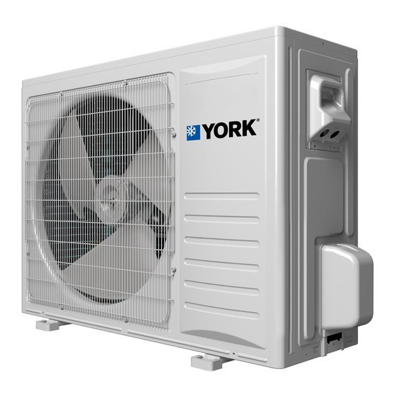
Personal safety equipment must be observed. must be used. Refrigerant cycle Figure 20: Refrigerant flow diagram Installation Manual: HMH7 Series - 17 SEER Horizontal Discharge Modulating Heat Pump Johnson Controls Ducted Systems... - Page 19 Figure 21: Outdoor unit - HMH72B24 Installation Manual: HMH7 Series - 17 SEER Horizontal Discharge Modulating Heat Pump Johnson Controls Ducted Systems...
- Page 20 Figure 22: Outdoor unit - HMH72B36 Installation Manual: HMH7 Series - 17 SEER Horizontal Discharge Modulating Heat Pump Johnson Controls Ducted Systems...
- Page 21 Figure 23: Outdoor unit - HMH72B48/HMH72B60 Installation Manual: HMH7 Series - 17 SEER Horizontal Discharge Modulating Heat Pump Johnson Controls Ducted Systems...
-
Page 22: Wiring Diagrams
Wait for more than 5 min before performing electrical work after power is removed. Figure 24: HMH72B24 and HMH72B36 electrical wiring diagram Installation Manual: HMH7 Series - 17 SEER Horizontal Discharge Modulating Heat Pump Johnson Controls Ducted Systems... - Page 23 Figure 25: HMH72B48 and HMH72B60 electrical wiring diagram For DIP switch settings, see Setting the DIP switch of the outdoor unit. Installation Manual: HMH7 Series - 17 SEER Horizontal Discharge Modulating Heat Pump Johnson Controls Ducted Systems...
-
Page 24: Control Board
Control board Figure 26: Main control board - HMH72B24/HMH72B36 Installation Manual: HMH7 Series - 17 SEER Horizontal Discharge Modulating Heat Pump Johnson Controls Ducted Systems... - Page 25 Figure 27: 7-segment display board - HMH72B24/HMH72B36 Installation Manual: HMH7 Series - 17 SEER Horizontal Discharge Modulating Heat Pump Johnson Controls Ducted Systems...
- Page 26 Figure 28: Main control board - HMH72B48/HMH72B60 Installation Manual: HMH7 Series - 17 SEER Horizontal Discharge Modulating Heat Pump Johnson Controls Ducted Systems...
- Page 27 Figure 29: Drive board Installation Manual: HMH7 Series - 17 SEER Horizontal Discharge Modulating Heat Pump Johnson Controls Ducted Systems...
-
Page 28: Field Settings
Change the switch from OFF to ON before applying power to the unit. Set the room thermostat to heating mode, which then operates the unit in manual defrosting mode. Installation Manual: HMH7 Series - 17 SEER Horizontal Discharge Modulating Heat Pump Johnson Controls Ducted Systems... -
Page 29: Running A Parameter Query
40 ft cannot be recovered into the outdoor unit and frequency requires recovery with external equipment. Compressor driving frequency Compressor target frequency Compressor discharge temperature Installation Manual: HMH7 Series - 17 SEER Horizontal Discharge Modulating Heat Pump Johnson Controls Ducted Systems... -
Page 30: Oil Trap
When the indoor unit is lower than the outdoor unit and the height difference is larger than 16 ft, install an oil trap every 16 ft in the suction piping. Installation Manual: HMH7 Series - 17 SEER Horizontal Discharge Modulating Heat Pump Johnson Controls Ducted Systems... -
Page 31: Control Mode
4.9853 5.1292 5.2726 -2.81 2.72 3.1632 3.2491 3.3353 -2.64 2.58 These are the parameters for the suction, ambient, coil, and discharge sensors: (R0=15K±2%, B0/100=3450K±2%) Installation Manual: HMH7 Series - 17 SEER Horizontal Discharge Modulating Heat Pump Johnson Controls Ducted Systems... -
Page 32: Troubleshooting
Checking components Check the refrigerant system. Test system flow Conditions: • The compressor is running. • The outdoor section is installed in a well-ventilated area. Installation Manual: HMH7 Series - 17 SEER Horizontal Discharge Modulating Heat Pump Johnson Controls Ducted Systems... - Page 33 Figure 38: Cooling mode flow chart Installation Manual: HMH7 Series - 17 SEER Horizontal Discharge Modulating Heat Pump Johnson Controls Ducted Systems...
- Page 34 Figure 39: Heating mode flow chart Installation Manual: HMH7 Series - 17 SEER Horizontal Discharge Modulating Heat Pump Johnson Controls Ducted Systems...
-
Page 35: Fault Codes
EE components fails. Replace the outdoor EE components control board control circuit fails. EEprom data error components. EE components are Reset the EE inserted incorrectly. components. Installation Manual: HMH7 Series - 17 SEER Horizontal Discharge Modulating Heat Pump Johnson Controls Ducted Systems... - Page 36 The low-voltage circuit and the short-circuit fuse is open. fuse. The low-voltage cable Choose suitable low- is incorrect. voltage cable. Refer to the installation instructions. Installation Manual: HMH7 Series - 17 SEER Horizontal Discharge Modulating Heat Pump Johnson Controls Ducted Systems...
- Page 37 Replace the temperature sensor The discharge discharge fault temperature sensor temperature sensor. has failed. Replace the outdoor The sampling circuit is control board. abnormal. Installation Manual: HMH7 Series - 17 SEER Horizontal Discharge Modulating Heat Pump Johnson Controls Ducted Systems...
- Page 38 The drive board has failed. Replace the drive board. The control board has failed. Replace the control board. Installation Manual: HMH7 Series - 17 SEER Horizontal Discharge Modulating Heat Pump Johnson Controls Ducted Systems...
- Page 39 The drive circuit of the board of the fan lower DC fan motor motor. has failed. Resolve the Outdoor airflow outdoor unit airflow blockage. restriction. Installation Manual: HMH7 Series - 17 SEER Horizontal Discharge Modulating Heat Pump Johnson Controls Ducted Systems...
- Page 40 The air inlet and/or outlet has been blocked. Remove the obstructions. The expansion valve or the capillary has failed. Replace the expansion valve or the capillary. Installation Manual: HMH7 Series - 17 SEER Horizontal Discharge Modulating Heat Pump Johnson Controls Ducted Systems...
- Page 41 System overload, current is Check the system. too high. Change the drive PFC overload current detection of Drive board fails. board. failure PFC fails. Change the PFC. Installation Manual: HMH7 Series - 17 SEER Horizontal Discharge Modulating Heat Pump Johnson Controls Ducted Systems...
- Page 42 Check the stop valve to Q axis current control error Drive board fails. see if it is open. Change the drive board. Installation Manual: HMH7 Series - 17 SEER Horizontal Discharge Modulating Heat Pump Johnson Controls Ducted Systems...
- Page 43 Bad drive board board. components. Change the Speed estimation, failure in drive Compressor shaft clamping. compressor. control The compressor insulation Change the has failed. compressor. Installation Manual: HMH7 Series - 17 SEER Horizontal Discharge Modulating Heat Pump Johnson Controls Ducted Systems...
- Page 44 Drive board fault. board. Compressor oil shortage, Change the Inverter overcurrent serious wear of crankshaft. compressor. The compressor insulation Change the has failed. compressor. Installation Manual: HMH7 Series - 17 SEER Horizontal Discharge Modulating Heat Pump Johnson Controls Ducted Systems...
- Page 45 Abnormal PFC drive loop. Change the drive board. Compressor drive chip could not Communication loop fault. Change the drive board. receive data from PFC chip Installation Manual: HMH7 Series - 17 SEER Horizontal Discharge Modulating Heat Pump Johnson Controls Ducted Systems...
-
Page 46: Troubleshooting Guide
The drainage pipe is blocked or Change the drainage pipe. broken. Correct the refrigeration piping Water leakage The insulation of the refrigerant insulation. piping is inadequate. Installation Manual: HMH7 Series - 17 SEER Horizontal Discharge Modulating Heat Pump Johnson Controls Ducted Systems... - Page 47 LED lamps are off when there is no failure, protection, or preheating. Figure 40: LED lamps Figure 41: Example - outdoor main control fault 32 Figure 42: Example - outdoor drive fault 32 Installation Manual: HMH7 Series - 17 SEER Horizontal Discharge Modulating Heat Pump Johnson Controls Ducted Systems...
- Page 48 The lamp of the drive board flashing shows that a failure has occurred. • The number of times the drive failure lamp flashes shows the failure code. Installation Manual: HMH7 Series - 17 SEER Horizontal Discharge Modulating Heat Pump Johnson Controls Ducted Systems...
-
Page 49: Start-Up Sheet
Start-up sheet Installation Manual: HMH7 Series - 17 SEER Horizontal Discharge Modulating Heat Pump Johnson Controls Ducted Systems... - Page 50 Subject to change without notice. Published in U.S.A. Copyright © 2021 by Johnson Controls. All rights reserved. Johnson Controls Ducted Systems...
Need help?
Do you have a question about the HMH7 Series and is the answer not in the manual?
Questions and answers