
Related Manuals for Bodyworx KRX700


Summary of Contents for Bodyworx KRX700
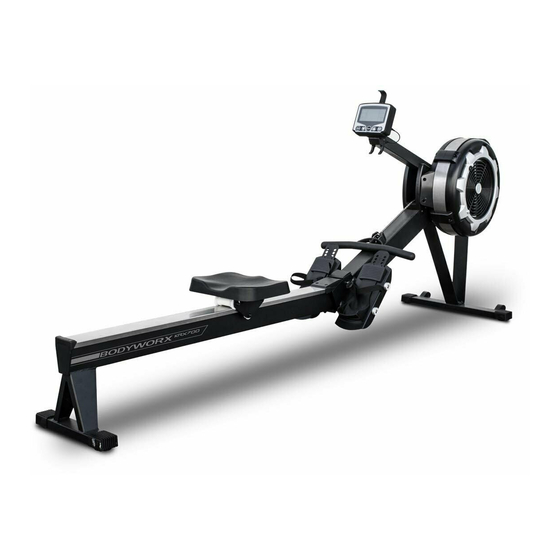
- Page 1 AIR ROWER Model No: KRX700 Retain this owner’s manual for future reference. Read and follow all instructions in this owner’s manual. Version A...
-
Page 2: Warranty Registration Form
GPI Sports & Fitness Warranty Registration Form Congratulations on purchasing your product, we at GPI believe that our product range is of the highest quality and represents great value for money. We back our product range up with our industry leading warranty. Please see below for the step by step instructions on how to register your product warranty online. - Page 3 IMPORTANT SAFETY INSTRUCTION............3 SAFETY GUIDELINES.................4 - 6 ASSEMBLY INSTRUCTION................. 7 - 12 OPERATING YOUR ROWER...............13 - 15 MAINTANENCE.................... 16 OPERATING THE CONSOLE..............17 - 21 MONITORING YOUR HEART RATE............22 PART LIST....................23 - 25 EXPLODED VIEW DIAGRAM..............26...
-
Page 4: Personal Safety During Assembly
from your physician. When using exercise equipment, you should always take basic precautions, including the following: Read all instructions before using the machine. These instructions are written to ensure your safety and to protect the unit. Do not allow children on or near the equipment. ... - Page 5 Successful cardio training programs have one prominent feature in common...safety. Cardio training has some inherent dangers, as do all physical activities. The chance of injury can be greatly reduced or completely removed by using correct running techniques, proper breathing, maintaining equipment in good working condition, and by wearing the appropriate clothing.
-
Page 6: Mechanical Safety
This exercise equipment is designed and built for optimum safety for home use. However, certain precautions always apply whenever you operate any exercise equipment. Be sure to read the entire manual before assembly and operation of this machine. Also, please note the following safety precautions. MECHANICAL SAFETY ... -
Page 7: Assembly Tips
Assembly of the machine takes professional installers about 1/2 hour to complete. If this is the first time you have assembled this type of equipment, plan on significantly more time. Professional installers are highly recommended! However, if you acquire the appropriate tools, obtain assistance, and follow the assembly steps sequentially, the process will take time, but is fairly easy. - Page 8 Attach Front/Rear support frame (7/8) to Front stabiliser (4). Lock by Hex round head bolt M6X16 (81) and Flat washer M6 (76). Do not tighten the bolts until Step 2.
- Page 9 Turn the fan rower over and put it on the Styrofoam (A)(B) as shown below picture. Do not put it on the ground to avoid damaging the chain cover. Attach Front/Rear support frame (7/8) to Main Frame (1) and lock by Hex round head bolt M6X16 (81) and Flat washer M6 (76). Tighten all the bolts.
- Page 10 Lift up the Main frame (1) and Monorail (2). Insert the Monorail (2) into the Main Frame (1). Make sure to lock the Folding axis (24) on the part (2a)
- Page 11 Put the pin (98) on. Lift up the Meter arm (6). And lock the Meter arm (6) on Left/Right side cover (57/58) with cross head bolt M6X10 (72).
- Page 12 Lock the Pedal set (5) on the Main frame (1) with the hex round head bolt M8X150 (84).
- Page 13 1. Insert the smart phone holder (20) into the meter (19). Tie up the smart phone holder (20) to the three bumps on the meter (19) with the elastic rope (21). 2. Lock the Meter (19) on the Meter holder (69) with Round head hex bolt M8X75 (78), Flat washer M8 (79), and Nylon nut M8 (80).
- Page 14 MOVING THE ROWER The rower is easy to move around safely. To move the rower: 1. Lift the rear of the rower 2. Roll the rower on its front transport wheels to the desire location. 3. Gently lower the rear of the rower to the ground level STORING THE ROWER The rower can be separated to minimise the unit size for storage.
-
Page 15: Damper Adjustment
DAMPER ADJUSTMENT There is a damper adjustment on the right side of the fan Shroud. The indicator can be moved up/down to adjust the damper. #1 is the lowest setting, #9 is the highest setting. HANDLEBAR POSITION Handlebar (#3) can be placed on the hook of the Console Monitor Post (#6) or it can be placed on the Handlebar Holder (#52). -
Page 16: Foot Pedal Adjustment
FOOT PEDAL ADJUSTMENT 1. Pull the Foot Pedal (#45) out of the two bulges of the Pedal Support Plate (#5). Bulges 2. Lower or raised the Foot Pedal to the desired location. 3. Lock the Foot Pedal (#45) by pressing the adjustment holes onto the Bulges. -
Page 17: Maintenance
Maintenance BUNGEE CORD ADJUSTMENT Over time, about 250,000 strokes on HANDLEBAR(3), your BUNGEE CORD(38) may stretch. Follow the following process to adjust: 1. Position the MAIN FRAME ASSEMBLY(1) as shown in the illustration. Remove the MAIN FRAME CAP(68) from the MAIN FRAME(1). Slid out the BOTTOM COVER(70) from the MAIN FRAME(1). -
Page 18: Console Display
CONSOLE DISPLAY TIME: - Display flashing “00:00” for presetting the TIME program. Time can be set from 1:00 to 99:00 minutes. - Displays the time during exercise. STROKE: - Display the total number of strokes during exercise PULSE: - Display the heart rate from 40 to 220 beats per minute during exercise. To use this function, the user must wear the Heart Rate Chest Strap. -
Page 19: Console Buttons
CALORIES: can be set from 10 to 999 cals PADDLE WIDTH: - Display the distance per stroke. STROKE RATE: - Display the current strokes per minute during exercise. DISTANCE: value can be set from 500 to 9999. CYCLE: - Display flashing “8” for presetting the number of cycles for the INTERVAL program. The value can be set from 1 to 99. -
Page 20: Initial Setup
ENTER/STOP BUTTON: - Press and hold the button for three seconds to reset the console program. - Press the button to pause the program during workout. INITIAL SETUP POWER ON: - Move the Handlebar or press any button. POWER OFF: - In IDLE mode, if there is no activity detected for 20 seconds, the console will shut - During all programs except 20/10, 10/20, 10/10 interval programs, the console will activity detected for two minutes. -
Page 21: Quick Start Program
1. QUICK START PROGRAM To Quick Start the program, you can pull on the Handlebar (#30) to start. All function values for the console will count up. For the other seven programs, press the “BACK” button to enter IDLE mode. Or press and hold the “ENTER/STOP”... - Page 22 Hit the four- d o t block, lose three The profile will move one interval per second. points. Matrix Display YOUR POSITION Hit the two-dot block Depends on your rowing speed score two points. and will move up and down, high rowing speed will go high and low rowing speed will go lower.
- Page 24 PART# DESCRIPTION Main Frame Rail Frame Handlebar Front Stabiliser Pedal Support Plate Console Monitor Post Front Support Leg A Front Support Leg B Foot Pedal End Cap Seat Carriage Bungee Cord Hook Chain Bracket Rail Perforated Steel Mesh ø ø Spacer, 8.2x 12x3.2mm...
- Page 25 PART# DESCRIPTION Damper Right Fan Shroud Left Fan Shroud Foot Pedal Foot Pedal Holder Pedal Strap ø ø Spacer, 16x30.5mm ø ø Pulley Spacer, 16x26.5mm Pulley Bushing Seat Handlebar Holder Upper Joint Cover Lower Joint Cover Generator Base Damper Cap Left Side Cover Right Side Cover Foot Cap...
- Page 26 PART# DESCRIPTION Socket Head Cap Screw, M8x40mm Phillips Flat Head Screw, M6x16mm Socket Head Cap Screw, M8x150mm Socket Head Cap Screw, M8x110mm Button Head Cap Screw, M8x25mm Lock Washer, M8 Phillips Head Screw, ST4.2x16mm Phillips Head Screw,, M5x8mm Socket Head Cap Screw, M5x92mm Hex Nut, M5 Chain Hook Elastic Ring...
-
Page 27: Exploded View Diagram
Exploded View Diagram... - Page 28 PROGRAMMABLE ROWER AIR ROWER Model No: KRX700 Model No: KR6000PRO To register your warranty, please go to www.gpisports.com.au...
Need help?
Do you have a question about the KRX700 and is the answer not in the manual?
Questions and answers