
Related Manuals for Bodyworx AC550M


Summary of Contents for Bodyworx AC550M
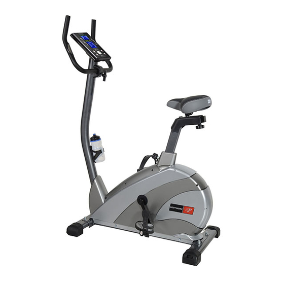
- Page 1 MANUAL MAG BIKE BODYWORX BODY WORX Model No: AC550M Retain this owner’s manual for future reference Read and follow all instructions in this owner’s manual Version A...
- Page 2 GPI Sport & Fitness Warranty Registration Form Congratulations on purchasing your product, we at GPI believe that our product range is of the highest quality and represents great value for money. We back our product range up with our industry leading warranty. Please see below for the step by step instructions on how to register your product warranty online.
-
Page 3: Table Of Contents
TABLE OF CONTENTS SAFETY PRECAUTIONS PRE-ASSEMBLY CHECK LIST EXPLODED DIAGRAM COMPUTER INSTRUCTIONS 12-16 HARDWARE PARTS LIST EXERCISE INSTRUCTIONS 17-18 IMPORTANT SAFETY PRECAUTIONS This exercise machine is built for optimum safety. However, certain precautions apply whenever you operate a piece of exercise equipment. Be sure to read the entire manual before you assemble or operate your machine. -
Page 4: Parts List
PARTS LIST Part No. Qty Part No. Description Description Main frame U type support tube Rear stabilizer Cover for seat post Front stabilizer Bushing for seat post Flat washer Φ10*Φ22*1.5 Spacer for seat post Domed nut M10 Quick release knob Carriage bolt M10*55 Cover for front post 7 L/R... -
Page 5: Exploded Diagram
EXPLODED DIAGRAM... -
Page 7: Hardware Parts List
HARDWARE PARTS LIST Description Drawing Flat washer Φ10*Φ22*1.5 Domed nut M10 Carriage bolt M10*55 Curved washer Φ8*20*1.5 Allen screw M8*16 T-type knob Cover for clamp Box wrench 13/19 Allen key 6mm Above described parts are all the parts you need to assemble this machine. Before you start to assemble, please check the hardware packing to make sure they are included. -
Page 8: Pre-Assembly Check List
PRE-ASSEMBLY CHECK LIST PART NO. DESCRIPTION Q’TY Main frame Rear stabilizer Front stabilizer Left pedal Right pedal Seat post Seat Front post Handlebar Bottle holder Bottle Cover for seat post Cover for front post User manual Hardware pack... -
Page 9: Assembly Instruction
ASSEMBLY INSTRUCTION STEP 1 Attach front stabilizer (3) to main frame (1), tighten with 2 sets of carriage bolt (6), flat washer (4) and domed nut (5). Attach rear stabilizer (2) to main frame (1), tighten with 2 sets of carriage bolt (6), flat washer (4) and domed nut (5). - Page 10 HOW TO CONNECT TENSION CONNECTOR Slide the Cable wire from the Upper Tension Connector in between the opening on the wire holder on the Lower Tension Connector. Pull Upper Tension Connector backward and slide the wire through the slot on the bracket.
- Page 11 STEP 3 Remove the clamp (32) and allen screw (16) from front post (13). Attach handlebar (14) to front post (13) and tighten with clamp (32), allen screw (16), cover for clamp (31) and T-type knob (30). Insert the hand pulse wires (28) through the grommet (29) and pull out from top bracket. Attach hand pulse wires (28) and sensor wire (25) to the computer (15) accordingly.
- Page 12 STEP 5 The left and right pedals (9 & 10) are marked “L” & “R”. Attach the straps to the pedals. Connect left pedal (9) to the left crank arm (46L). The left pedal is on the left hand side of the cycle as you sit on it.
-
Page 13: Computer Instructions
COMPUTER INSTRUCTIONS DISPLAY FUNCTIONS ITEM DESCRIPTION Display the rotation per minute with range from 0~15 to 999. Display current training speed. Maximum speed is 99.9 KM/H or SPEED ML/H. Count up - No preset target, Time will count up from 00:00 to maximum 99:59 with each increment is 1 minute. - Page 14 BOTTON FUNCTION ITEM DESCRIPTION With PULSE input, press [RECOVERY] to test heart rate recovery RECOVERY status. MODE Confirm setting or selection. JOGGLE Use the joggle wheel to select an exercise program (G1~G4) and also WHEEL to set up value for TIME, DISTANCE, CALORIES and PULSE. To clear settings of TIME, DISTANCE, CALORIES and PULSE.
- Page 15 reset TIME or press RESET key to back to G1~G4 selection. Whenever there is RPM signal in, system will START directly, STOP symbol will be crush ② out (Figure 7). When TIME counts down to 0, beeper will sound 4 alarm/s for 8s. Press any key to stop the alarm, then system continue to count up.
- Page 16 Figure 9 Figure10 Figure 11 When TIME counts down to 0, STOP symbol is light up, beeper will sound 4 alarm/s for ③ 8s. Meanwhile, system will display victory picture and stop all calculations. Press any key to stop the alarm. STOP symbol will be crush out, System continue to cycle count down. System will enter into Power-saving mode if there is no RPM signal for 4 minutes.
- Page 17 4. RECOVERY mode After exercising for a period of time, keep holding on handgrips and press [RECOVERY]. All function display will stop except “TIME” that will start counting down from 00:60 to 00:00. LCD will display your heart rate recovery status with the F1, F2….to F6.F1 is the best, F6 is the worst.
-
Page 18: Exercise Instructions
EXERCISE INSTRUCTIONS Using your MANUAL MAG BIKE will provide you with several benefits, it will improve your physical fitness, tone muscle and in conjunction with a calorie controlled diet help you lose weight. 1. The Warm Up Phase This stage helps get the blood flowing around the body and the muscles working properly. It will also reduce the risk of cramp and muscle injury. - Page 19 This stage is to let your Cardio-vascular System and muscles wind down. This is a repeat of the warm up exercise e.g. reduce your tempo, continue for approximately 5 minutes. The stretching exercises should now be repeated, again remembering not to force or jerk your muscles into the stretch.
- Page 20 BODYWORX BODYWORX Model No: AC550M To register your warranty, please go to www.gpisports.com.au...
Need help?
Do you have a question about the AC550M and is the answer not in the manual?
Questions and answers