Table of Contents
Advertisement
Quick Links
Download this manual
See also:
Operator's Manual
Advertisement
Table of Contents

Related Manuals for Topcon HiPer Lite


Summary of Contents for Topcon HiPer Lite
- Page 1 PRECISION GPS+: HiPer Lite HiPer Operator’s Manual...
- Page 3 Rev A ©Copyright Topcon Positioning Systems, Inc. June, 2003 All contents in this manual are copyrighted by Topcon. All rights reserved. The information contained herein may not be used, accessed, copied, stored, displayed, sold, modified, published, or distributed, or otherwise reproduced without express written consent from Topcon.
- Page 4 ECO#2049...
-
Page 5: Table Of Contents
able of Contents Preface ..............xi Terms and Conditions ............xi Regulatory Information ........... xiv Manual Conventions ............xvi Chapter 1 Introduction ............1-1 Overview ................1-2 Principles of Operation ............ 1-2 GPS Overview ............1-2 Calculating Positions .......... 1-3 GPS Positioning .......... - Page 6 External Batteries ............2-3 Battery Charger ............2-4 Turning On/Off the HiPer Lite ........2-4 Connecting the HiPer Lite and a Computer ..... 2-4 Establishing a Wireless Connection ......2-5 Establishing an RS232 Cable Connection ....2-6 Establishing a PC-CDU Connection ......2-6 HiPer Lite Configuration ..........
- Page 7 Downloading Files to a Computer ........4-9 Deleting Files ..............4-12 Checking an OAF ............4-14 Loading OAFs ..............4-16 Managing HiPer Lite Memory ......... 4-17 Clearing the NVRAM ............4-17 Using MINTER to Clear NVRAM ......4-18 Using PC-CDU to Clear NVRAM ......4-18 Changing Receiver Modes ..........
- Page 8 Table of Contents Appendix A Specifications ............A-1 HiPer Lite Specifications ..........A-1 Connector Specifications ..........A-9 Radio (Modem) RF Connector ........A-9 Power Connector ............A-10 Serial C-RS232 Connector ........A-11 Appendix B Safety Warnings ........... B-1 General Warnings ............B-1 Internal Battery Pack Warnings ........
- Page 9 Figures Chapter 1 Introduction ............1-1 HiPer Lite Receiver ............1-1 HiPer Lite Radome ............1-13 HiPer Lite Front Panel ............. 1-14 HiPer Lite Back Panel ............. 1-15 Chapter 2 Configuration ............2-1 PC-CDU Main Screen ............. 2-7 Click File->Connect ............
- Page 10 Receiver Configuration – Positioning ......3-11 Base Tab Configuration ........... 3-12 Base Configuration – Ports ..........3-13 HiPer Lite Rover Station Setup ........3-14 Rover Tab Configuration ..........3-15 Rover Configuration – Ports ..........3-17 PC-CDU Main Screen ............3-17 Topcon HiPer Lite Operator’s Manual...
- Page 11 List of Figures Chapter 4 Operation .............. 4-1 MINTER ................4-1 Connection Parameters – RTS/CTS Handshaking ..4-9 File->File Manager ............4-9 Find Files to Download ........... 4-10 Download Files ..............4-11 Download Files – Status Indicators ......... 4-11 Click Disconnect then Exit ..........4-12 Connection Parameters –...
- Page 12 LIst of Figures Notes: viii Topcon HiPer Lite Operator’s Manual...
- Page 13 Configuration ............2-1 Data Recording Parameter Behavior ....... 2-27 Chapter 3 Setup and Survey ........... 3-1 HiPer Lite Antenna Offset Values for GD Options ..3-3 Chapter 4 Operation ............... 4-1 FN Key Functions and REC LED Status ......4-4 Signal-to-Noise (S/N) “Good”...
- Page 14 List of Tables Notes: Topcon HiPer Lite Operator’s Manual...
-
Page 15: Preface
Manual without TPS’ express written consent and may only use such information for the care and operation of your HiPer Lite. The information and data in this Manual are a valuable asset of TPS and 1-866-4TOPCON www.topconpositioning.com... - Page 16 TPS. Windows® is a registered trademark of Microsoft Corporation. Bluetooth™ is a trademark owned by Bluetooth SIG, Inc. and is used by Topcon Positioning Systems, Inc. under license. Product and company names mentioned herein may be trademarks of their respective owners.
- Page 17 Software under the terms stated herein and in any case only with a single HiPer Lite or single computer. You may not assign or transfer the Software or this license without the express written consent of TPS.
-
Page 18: Regulatory Information
Conditions (including the Software license, warranty and limitation of liability). SAFETY – Improper use of the HiPer Lite can lead to injury to persons or property and/or malfunction of the product. The HiPer Lite should only be repaired by authorized TPS warranty service centers. - Page 19 Regulatory Information installations. This equipment generates, uses, and can radiate radio frequency energy, and if not installed and used in accordance with the instructions, may cause harmful interference to radio communications. However, there is no guarantee that interference will not occur in a particular installation.
-
Page 20: Manual Conventions
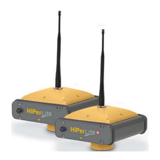
WARNING Notification that an action will result in system damage, loss of data, loss of warranty, or personal injury. ANGER NDER NO CIRCUMSTANCES SHOULD THIS ACTION BE PERFORMED Topcon HiPer Lite Operator’s Manual... - Page 21 Chapter 1 ntroduction This chapter describes: • The HiPer Lite (Figure 1-1) • GPS and your receiver • Common HiPer Lite functions • Standard package contents and configurations • HiPer Lite components • The Option Authorized File (OAF) Figure 1-1. HiPer Lite Receiver 1-866-4TOPCON www.topconpositioning.com...
-
Page 22: Chapter 1 Introduction
The HiPer Lite can receive and process both L1 and L2 signals, improving the accuracy of your survey points and positions. The dual-frequency and GPS+ features of the HiPer Lite combine to provide the only real time kinematic (RTK) system accurate for short and long baselines. -
Page 23: Calculating Positions
Principles of Operation any one time, with a standard 15 degree angle, up to 10 or 12 GPS satellites are visible from any point on earth. When a receiver can also track GLONASS satellites, between 10 and 16 satellites are visible. The GPS and GLONASS network has three components: •... -
Page 24: Gps Positioning
DOP number, providing more accurate positioning. • Availability – The availability of satellites affects the calculation of valid positions. The more visible satellites available, the more valid and accurate the position. Natural and man-made objects can block, Topcon HiPer Lite Operator’s Manual... -
Page 25: Conclusion
–Several algorithms to detect and correct faulty information. Conclusion Surveyors can use Topcon GPS+ receivers to collect data from a network of satellites and control stations to triangulate precise points anywhere on Earth. This overview simply outlines the basics of GPS and GLONASS positioning. -
Page 26: Chapter 1 Introduction
RTK mode, raw data measurements can also be recorded into the receiver’s internal memory. This allows the operator to double check real-time results obtained in the field. Depending on your options, capabilities of the HiPer Lite receiver include: • Co-Op Tracking •... -
Page 27: Standard Package Contents
Standard Package Contents The HiPer Lite comes in a real-time kinematic (RTK) package with two HiPer Lite receiver, one as a Base Station and the other as a Rover Station (also, refer to the re-packaging instruction card). The contents of this package include: •... -
Page 28: Software
Topcon website (www.topcongps.com/software/index.html or http://www.topcongps.com/software/3rdparty.html). The following software will also be useful for operating, caring for and using your HiPer Lite receiver, and may be required for some applications. • FLoader – Topcon’s firmware loader; available on the Topcon website. -
Page 29: Getting Acquainted
The HiPer Lite is also versatile and can be configured in several different ways. The casing allocates space for two nonremovable, on-board Li-Ion batteries, a Bluetooth™... -
Page 30: Internal Components
L1/L2 signals. Bluetooth Module A combination of software and hardware technology that makes the HiPer Lite a mobile, wireless, GPS+ receiver that supports a point-to-point serial profile. As such, the HiPer Lite can transfer and synchronize files between the receiver and any other Bluetooth wireless technology... -
Page 31: Power Board
GPS receiver board and power board must be loaded with firmware from the same package. GPS+ Receiver Board The HiPer Lite is supplied with a Euro-80 card capable of processing GPS L1/L2 signals. Table 1-1lists the options available for this card. -
Page 32: Battery
GPS receiver should run at least 18 hours with fully charged on-board batteries. The Li-Ion batteries used in the HiPer Lite should run at no less than 98% capacity after 500 charging cycles. These batteries do not need to be drained before recharging. -
Page 33: Radome
Getting Acquainted Radome Figure 1-2 shows the radome components. Figure 1-2. HiPer Lite Radome • Internal antenna – Location of GPS/GLONASS internal antenna. • Modem antenna connector – Modem antenna connector used for internal modem RF connection. This is a TNC female connector for spread spectrum modems. -
Page 34: Front Panel
Figure 1-3 shows front panel components. MINTER Reset Slant Height Measure Mark Figure 1-3. HiPer Lite Front Panel • MINTER – The Minimum INTERface for the HiPer Lite receiver. The MINTER consists of two keys and up to four, three-color LEDs. See “Using the MINTER”... -
Page 35: Back Panel
Figure 1-4 shows the back panel components. Vent Plug Slant Height Measure Mark Figure 1-4. HiPer Lite Back Panel • Vent plug – Equalizes the pressure between the inside of the receiver and the outside environment. • Slant height measure mark (SHMM) -
Page 36: Option Authorized File (Oaf)
HiPer Lite according to particular needs, thus only purchasing those options needed. Typically, all HiPer Lite receivers ship with a temporary OAF that allows the receiver to be used for a predetermined period of time. When the receiver is purchased, a new OAF activates desired, purchased options permanently. -
Page 37: Configuration
1. Charge the batteries. See “Powering the HiPer Lite” on page 2-2. 2. Configure the various parts of your receiver. See: • “Connecting the HiPer Lite and a Computer” on page 2-4, • “HiPer Lite Configuration” on page 2-9, • “MINTER Configuration” on page 2-20, •... -
Page 38: Powering The Hiper Lite
See “Power Management” on page 2-14 for more information. The Li-Ion batteries used in the HiPer Lite should run at no less than 98% capacity after 500 charging cycles. These batteries do not need to be drained before recharging. -
Page 39: External Batteries
Powering the HiPer Lite External Batteries In addition to the internal batteries, you can use your HiPer Lite with external batteries. The use of external batteries allows you to continue using the receiver in case the internal batteries are discharged. To use external batteries, you must have: •... -
Page 40: Battery Charger
Battery Charger The same charger used to charge the internal batteries can be used as an external power supply for the HiPer Lite receiver. The charger is provided with the receiver package. 1. Connect the battery charger to the power port on the HiPer Lite front panel. -
Page 41: Establishing A Wireless Connection
Port B are: 115200 bps, 8 data bits, 1 stop bit, no parity, and no handshaking. The HiPer Lite and external device connection procedure varies slightly depending on the type of external device used. In general, the connection procedure is as follows:... -
Page 42: Establishing An Rs232 Cable Connection
PC-CDU is a Personal Computer-Control Display Unit software used to manage the various functions of your receiver. The full range of PC-CDU configuration and function is outside the scope of this manual. For more information on any Topcon HiPer Lite Operator’s Manual... -
Page 43: Pc-Cdu Main Screen
Connecting the HiPer Lite and a Computer of the procedures in this section or on PC-CDU, refer to the PC-CDU User’s Manual available on the TPS website. 1. Once the receiver and a computer are connected, start PC- CDU on your computer. The PC-CDU main screen displays (Figure 2-1). -
Page 44: Pc-Cdu Connection Established
Once a connection has been established, the COM port and baud rate display in the lower-left corner of the main window of PC-CDU. A timer begins to count up in the lower-right corner as well (Figure 2-4). Figure 2-4. PC-CDU Connection Established Topcon HiPer Lite Operator’s Manual... -
Page 45: Hiper Lite Configuration
HiPer Lite Configuration HiPer Lite Configuration You use PC-CDU to configure the various parts of the HiPer Lite receiver. Any settings you make using PC-CDU will be saved in the receiver’s memory, and will be reflected when you use the MINTER. -
Page 46: Receiver Configuration
• Enter the File name prefix. Use the last three digits of the receiver serial number.The receiver’s serial number and part number can be found on the bottom panel of the receiver. 2-10 Figure 2-7. Receiver Configuration – MINTER Tab Topcon HiPer Lite Operator’s Manual... -
Page 47: Receiver Configuration - Advanced Tab
HiPer Lite Configuration If your jobsite is in an area that has obstructions (buildings, trees, etc.), and/or the antenna location is near reflective objects, configure the receiver to reduce errors from these sources. WARNING Do not make other changes without consulting the PC-CDU User’s Manual. -
Page 48: Advanced Configuration - Multipath Reduction
• Carrier multipath reduction Figure 2-9. Advanced Configuration – Multipath Reduction 6. Click the Loop Management tab, enable the following boxes, and click Apply (Figure 2-10 on page 2-13). • Enable Co-Op tracking • Static Mode 2-12 Topcon HiPer Lite Operator’s Manual... -
Page 49: Advanced Configuration - Loop Management
HiPer Lite Configuration Figure 2-10. Advanced Configuration – Loop Management 7. Click OK to close the Receiver Configuration screen. 8. Click on File->Disconnect, then File->Exit to quit PC-CDU (Figure 2-11). Figure 2-11. Click Disconnect then Exit NOTICE Disconnecting the receiver from the computer before exiting will eliminate any possible conflict in the management of your serial ports. -
Page 50: Power Management
To access the tab controlling the power settings of your receiver, take the following steps: 1. Connect your receiver and computer. See “Connecting the HiPer Lite and a Computer” on page 2-4 for this procedure. 2. Once connected, click Configuration->Receiver (Figure 2-12). - Page 51 HiPer Lite Configuration • Auto – receiver automatically selects the power source. • Mix – receiver automatically detects and consumes power from the source with the largest voltage. • Battery A – receiver consumes power from battery A. • Battery B – receiver consumes power from battery B.
-
Page 52: Select Power Output Modes - Ports
• Off – the power is absent, even if the receiver is on. • Always – the power board delivers voltage on pin one of all serial port connectors, even if the receiver is off. 2-16 Topcon HiPer Lite Operator’s Manual... -
Page 53: Select Power Output Modes - Slots
HiPer Lite Configuration 6. Select the Power output modes Slots drop-down list to set power output on internal slots (Figure 2-16). Figure 2-16. Select Power Output Modes – Slots • On – all slots have power if the receiver is turned on. -
Page 54: Enable And Apply Power Settings
(Figure 2-18). 9. Select and check the Enable Low Power Mode check box to put the receiver’s processor into low power consumption mode (Figure 2-18). Figure 2-18. Enable and Apply Power Settings 10. Click Apply. 2-18 Topcon HiPer Lite Operator’s Manual... -
Page 55: Charging Internal Batteries
HiPer Lite Configuration Charging Internal Batteries Use one of the following conditions for maximum battery charge speed. • The receiver is turned off. Power Mode and Charger Mode are set to Auto. See “Power Management” on page 2-14 for setting these parameters. -
Page 56: Checking Internal Battery Status
• Click on Help->About and view the battery voltages on the About PC-CDU screen. MINTER Configuration The HiPer Lite Minimum INTERface (MINTER) consists of two keys (Power and FN) and up to four LEDs (STAT, REC, BATT, and RX) that control and display the receiver’s operation (Figure 2-19). - Page 57 • Show the status (high charge, intermediate charge, or low charge) of the battery (BATT LED). • Show the power source for the HiPer Lite (BATT LED). • Show the status of the modem and if it receives signals (RX LED).
-
Page 58: Configuration->Receiver
• Always append to the file on page 2-24 • Files Creation mode on page 2-24 • Automatic File Rotation Mode (AFRM) on page 2-24 • FN key mode on page 2-26 2-22 • Initial data collection dynamic mode on page 2-26 Topcon HiPer Lite Operator’s Manual... -
Page 59: Receiver Configuration - Minter Tab
MINTER Configuration • Data recording auto-start on page 2-26 Figure 2-22. Receiver Configuration – MINTER Tab Recording Interval parameter This parameter specifies the message output interval into the log file when the MINTER FN key (pressed for 1–5 seconds) activates data logging. This setting is used for both logging a single log file, and logging receiver data in AFRM mode. -
Page 60: Always Append To The File
When opening a new log file, the receiver enables the default set of messages outputted with the default output period. Both the default set of messages and the default output period are programmable. 2-24 Topcon HiPer Lite Operator’s Manual... - Page 61 MINTER Configuration • Period – specifies the time duration of each log file created in AFRM mode. Values are 60 to 86400 seconds. The default value is 3600 seconds. • Phase – specifies the “phase” (constant time shift) of creating multiple log files in AFRM mode.
- Page 62 Table 2-1 on page 2-27 gives the different scenarios available and the results after power is restored to the receiver. “Specified file” refers to the file name entered in the Always append to file 2-26 parameter. Topcon HiPer Lite Operator’s Manual...
- Page 63 MINTER Configuration Table 2-1. Data Recording Parameter Behavior Enabled Radio Button Results Before Power Failure Always Data logging will Receiver will Receiver will Receiver data not resume when resume data resume data logged to file power is restored. logging to the logging to the same specified.
-
Page 64: Radio Configuration
First, download and install Modem-TPS, then connect your computer and the receiver, and run the configuration program. NOTICE Your receiver may be configured without a radio modem. If this is the case, please skip to “Collecting Almanacs” on page 2-40. 2-28 Topcon HiPer Lite Operator’s Manual... -
Page 65: Run Modem-Tps
Radio Configuration 1. On your computer, click Start->Run to open the Run dialog box. Click the Browse button to find the Modem-TPS setup.exe program, and click OK (Figure 2-23). Figure 2-23. Run Modem-TPS 2. On the Modem-TPS Installation dialog box, select the directory in which to install the program, or keep the default directory, and click Finish (Figure 2-24). -
Page 66: Modem-Tps Installation Complete
1. Using the RS232 cable, connect the serial port of your computer (usually COM1) to the receiver’s serial port A. 2. Press the power buttons on the receiver and computer or external controller to turn them on. 2-30 Topcon HiPer Lite Operator’s Manual... -
Page 67: Modem-Tps Connection Dialog Box
Radio Configuration 3. Start Modem-TPS. On the Connection dialog box, select the computer serial port your receiver is connected to and click Connect (Figure 2-28). Figure 2-28. Modem-TPS Connection Dialog Box Once a connection has been established, the COM port and baud rate will be displayed in the lower-left corner of the main window of Modem-TPS. -
Page 68: Modem-Tps Radio Link Tab
The same rate must be used for both the receiver and the modem. • RTS/CTS – controls the flow of data between the receiver and modem. Select On to enable handshaking/hardware 2-32 flow control; select Off to disable handshaking. Topcon HiPer Lite Operator’s Manual... -
Page 69: Modem-Tps Serial Interface Tab
Radio Configuration Figure 2-30. Modem-TPS Serial Interface Tab 6. Click the Identification tab to view information on the modem type, firmware version, board revision, and serial number (Figure 2-31). Figure 2-31. Modem-TPS Identification Tab 2-33 1-866-4TOPCON www.topconpositioning.com... -
Page 70: About Modem-Tps
About Modem-TPS dialog box (Figure 2-32). Figure 2-32. About Modem-TPS 8. Click File->Disconnect (Figure 2-33), then click File->Exit to quit the program. Continue with other configuration or operation functions as needed. Figure 2-33. Click Disconnect then Exit 2-34 Topcon HiPer Lite Operator’s Manual... -
Page 71: Bluetooth Module Configuration
Bluetooth Module Configuration Bluetooth Module Configuration Use BTCONF, the Bluetooth module’s configuration program, and your computer to: • access the Bluetooth wireless technology module • configure the Bluetooth module • check or change the module’s configuration To access the Bluetooth wireless technology module, first download and install BTCONF, then connect your computer and the receiver and run the configuration program. -
Page 72: Bluetooth Module Configuration Main Screen
For BTCONF version and copyright information, click the About button. 4. From the drop-down list in the upper left corner, select the computer serial port (usually COM1) used for communication (Figure 2-35). 2-36 Figure 2-35. Select Communication Port and Click Connect Topcon HiPer Lite Operator’s Manual... - Page 73 Bluetooth Module Configuration 5. Click Connect to connect the computer and Bluetooth module (Figure 2-35 on page 2-36). Once the receiver and computer connect through BTCONF, the Identification tab (Figure 2-36) displays the following information: • Bluetooth name – the name of the Bluetooth module, set in the Parameters tab.
- Page 74 Bluetooth enabled devices (such as, the receiver and a computer) can establish a communication link. The two devices must use the same PIN. NOTICE If you do not need security settings, leave these parameters disabled. 2-38 Topcon HiPer Lite Operator’s Manual...
- Page 75 Bluetooth Module Configuration Figure 2-38. BTCONF Security Parameters 9. Click the Serial Interface tab (Figure 2-39). Enable Echo to display Bluetooth module replies and corresponding commands on the computer terminal. If needed, click Apply. Figure 2-39. BTCONF Serial Interface Tab 2-39 1-866-4TOPCON www.topconpositioning.com...
-
Page 76: Collecting Almanacs
Non-Volatile Random Access Memory (NVRAM). 1. Set up the receiver (connect the external antenna if needed) in a location with a clear view of the sky. 2. Turn on the receiver. 2-40 Topcon HiPer Lite Operator’s Manual... - Page 77 Collecting Almanacs NOTICE If 15 minutes have passed and the receiver does not lock on to satellites, you may need to clear the NVRAM. See “Clearing the NVRAM” on page 4-17 for this procedure. You will need to collect or update the almanac: •...
- Page 78 Configuration Notes: 2-42 Topcon HiPer Lite Operator’s Manual...
-
Page 79: Setup And Survey
• RTK Base station setup • RTK Rover setup • Basic surveying with the HiPer Lite The HiPer Lite package uses one receiver as the Base station and the other as the Rover station. HiPer Lite Receiver Setup To set up the HiPer Lite receivers you must: 1. -
Page 80: Step 1: Set Up Hiper Lite Receiver
This section assumes the receiver has been configured using PC-CDU. 1. Place the HiPer Lite on the appropriate tripod or bipod. 2. Center the receiver over the point at which data will be collected. For most applications, this should be at a location with a clear view of the sky. -
Page 81: Hiper Lite Antenna Offsets
• SHMM to ARP vertical offset = 30.50mm • SHMM to ARP horizontal offset = 77.75mm Table 3-1gives the offset values for HiPer Lite receivers. Table 3-1. HiPer Lite Antenna Offset Values for GD Options To L1 Phase Center To L2 Phase Center 102.0mm... -
Page 82: Step 3: Collect Data
2. Release the FN key when the REC (recording) LED light turns green. This indicates that a file has opened and data collection has started. The REC LED blinks each time data is saved to the internal memory. Topcon HiPer Lite Operator’s Manual... -
Page 83: Surveying With The Hiper Lite
4. To turn off the receiver, press and hold the power key until all lights go out, then release. Surveying with the HiPer Lite The HiPer Lite receiver can be used to perform the following types of surveying: • Static •... - Page 84 Static Survey using MINTER. 1. Connect your receiver and computer. See “Connecting the HiPer Lite and a Computer” on page 2-4 for this procedure. 2. Open PC-CDU, click Configuration->Receiver ->MINTER and specify the following parameters, then click Apply (Figure 3-2 on page 3-7): •...
-
Page 85: Configuration->Receiver->Minter
Surveying with the HiPer Lite • File Name Prefix – last 3 digits of receiver’s serial number • LED blink mode switch – enable to start and stop static data recording using the FN key Figure 3-2. Configuration->Receiver->MINTER 3. Click the Advanced tab and then the Multipath tab, set the following parameters, then click Apply (Figure 3-3): •... -
Page 86: Kinematic (Stop And Go) Survey
1. Using PC-CDU, configure and set up the Base as described in “Static Survey” on page 3-5. 2. Using PC-CDU, click Configuration->Receiver ->MINTER, and configure the Rover with the following parameters, then click Apply (Figure 3-5 on page 3-9): Topcon HiPer Lite Operator’s Manual... - Page 87 Surveying with the HiPer Lite • FN Key Mode, Occupation Mode Switch – enable • Initial data collection dynamic mode, Static – enable See Table 4-1 on page 4-4 for FN key functions and REC LED statuses. Figure 3-5. Rover MINTER Configuration...
-
Page 88: Real-Time Kinematic Survey
2. Press the power key on the receiver. 3. Check the STAT light for tracked satellites. 4. Connect your receiver and computer. See “Connecting 3-10 the HiPer Lite and a Computer” on page 2-4 for this procedure. Topcon HiPer Lite Operator’s Manual... -
Page 89: Receiver Configuration - Positioning
Surveying with the HiPer Lite 5. Click Configuration->Receiver. 6. Click Set all parameters to defaults located at the bottom of the dialog box (Figure 3-6). Figure 3-6. Set All Parameters to Defaults 7. On the Receiver Configuration screen, select the MINTER tab. -
Page 90: Base Tab Configuration
Click Refresh if the coordinates are zeros. NOTICE The reference geodetic coordinates specified on this tab relate to the antenna L1 phase center. 3-12 Figure 3-8. Base Tab Configuration Topcon HiPer Lite Operator’s Manual... -
Page 91: Base Configuration – Ports
Surveying with the HiPer Lite 10. Select the Ports tab and set the following port parameters (Figure 3-9). Use serial port C for an internal Spread Spectrum 915 MHz modem. • Output drop-down list – select type and format of differential corrections. -
Page 92: Setting Up An Rtk Rover
1. Set up the Rover station receiver’s antenna as described in “HiPer Lite Receiver Setup” on page 3-1. 2. Connect the receiver and computer. See “Connecting the HiPer Lite and a Computer” on page 2-4. 3. Click Configuration->Receiver. 4. Select the Positioning tab and set the Position Masks,... -
Page 93: Rover Tab Configuration
Surveying with the HiPer Lite 5. Select the Rover tab and set the desired Positioning Mode (Figure 3-11). Figure 3-11. Rover Tab Configuration Adjust the following RTK Parameters settings: • Under RTK mode in the RTK Parameters section, choose either Extrapolation for RTK float (kinematic) or Delay for RTK fixed (static). - Page 94 • Baud rate drop-down list – select a baud rate (i.e., the rate at which differential messages will be transmitted from modem to receiver). For Spread Spectrum 915 MHz modems, use a 19200 baud rate. 3-16 Topcon HiPer Lite Operator’s Manual...
-
Page 95: Pc-Cdu Main Screen
Surveying with the HiPer Lite Figure 3-12. Rover Configuration – Ports 7. Click Apply. 8. Click OK to close the Receiver Configuration screen. 9. On the main screen (Figure 3-13), check the LQ field to ensure the receiver obtains differential corrections. - Page 96 If the receiver is not (for some reason) receiving differential corrections, or if none of the ports has been configured to receive differential corrections, the LQ field will either be empty or it will look like this: 100%(999,0000,0000). 3-18 Topcon HiPer Lite Operator’s Manual...
-
Page 97: Operation
Chapter 4 peration This chapter describes standard HiPer Lite operating procedures: • Using the MINTER • Downloading HiPer Lite files to a computer • Deleting files from the HiPer Lite • Checking and loading OAFs • Managing HiPer Lite memory •... -
Page 98: Power Key
(normal and extended information), or between static and dynamic post- processing modes, depending on the receiver's configuration. During the first second of pressing the FN key, the REC LED is orange. Topcon HiPer Lite Operator’s Manual... - Page 99 Using the MINTER • Pressing the FN key for more than one and less than five seconds will start/stop data recording. During data recording the REC LED is green. If the REC LED is red, the receiver has run out of memory, has a hardware problem, or contains an improper OAF (see “Option Authorized File (OAF)”...
-
Page 100: Chapter 4 Operation
Green Release to start recording (Kinematic or Static post-processing occupation mode) Pressed for 5–8 Release to turn serial port A baud rate seconds to 9600 bps. Pressed for > 8 No light No function. seconds Topcon HiPer Lite Operator’s Manual... - Page 101 Using the MINTER Table 4-1. FN Key Functions and REC LED Status FN Key REC LED Status When data recording is on, and the FN key is... No free memory; hardware problem with data recording. If FN key mode is “LED blink mode switch” Green Data recording started (post-processing occupation mode undefined).
-
Page 102: Battery Led
• Blinking once a second – the batteries are being charged. • Blinking once every five seconds – the HiPer Lite uses the internal batteries for power. • Not blinking – the receiver is in Zero Power Mode or the internal batteries are completely discharged and no external power is connected. -
Page 103: Information Modes
• Red flashes plus Green flashes – the modem is in command mode. Information Modes The HiPer Lite has two information modes: Normal and Extended Information Mode (EIM). Normal In normal mode, the STAT LED indicates the number of tracked satellites and the position’s computation status. - Page 104 15 minutes of powering on. • Green – ok • Orange – wait • Red – some tests failed 3. To switch back to normal, press the FN key. Topcon HiPer Lite Operator’s Manual...
-
Page 105: Downloading Files To A Computer
HiPer Lite. 1. Connect your receiver and computer. See “Connecting the HiPer Lite and a Computer” on page 2-4 for this procedure. 2. On the Connection Parameters dialog box, enable RTS/CTS handshaking (Figure 4-2). -
Page 106: Find Files To Download
7. Select the file(s) to download (Figure 4-5 on page 4-11). To select multiple files, hold down the shift key and click on nonsequential files to select several files at once; or, hold down the Ctrl key and click on individual files. 4-10 Topcon HiPer Lite Operator’s Manual... -
Page 107: Download Files
Downloading Files to a Computer Figure 4-5. Download Files 8. Click the Download button. During the download, status indicators display next to each file (Figure 4-6). • Blue indicator – file in queue for downloading. • Red indicator – file currently downloading. •... -
Page 108: Deleting Files
Use the following steps to delete files from your receiver. 1. Connect your receiver and computer. See “Connecting the HiPer Lite and a Computer” on page 2-4 for this procedure. 2. On the Connection Parameters dialog box, enable RTS/CTS handshaking (Figure 4-8). -
Page 109: File->Manager
Deleting Files 3. Click File->File Manager (Figure 4-9). Figure 4-9. File->Manager 4. On the Download files tab, select the file(s) you want to delete (Figure 4-10). To select multiple files, hold down the shift key and click on nonsequential files to select several files at once; or hold down the Ctrl key and click on individual files. -
Page 110: Checking An Oaf
Refer to the PC-CDU User’s Manual for a more complete description of the PC-CDU software. 1. Connect your receiver and computer. See “Connecting the HiPer Lite and a Computer” on page 2-4 for this procedure. 2. Click Tools->Receiver Options (Figure 4-11). Figure 4-11. Tools->Receiver Options... -
Page 111: Option Manager
Checking an OAF • -1 or “-----” – the firmware version does not support this option. • 0 – the receiver option is disabled. • positive integer – the option is enabled. • yes or no – the option is either enabled or disabled. Figure 4-12. -
Page 112: Loading Oafs
Operation Loading OAFs Topcon Positioning System dealers provide customers with OAF files. For any OAF related questions, E-mail TPS at options@topconps.com. Please have your receiver ID number available (see “Checking Firmware Version” on page 4-21). 1. To load a new OAF, follow steps one and two in “Checking an OAF”... -
Page 113: Managing Hiper Lite Memory
NVRAM can eliminate communication or tracking problems. Clearing the NVRAM in your HiPer Lite can be interpreted as a “soft boot” in your computer. After clearing the NVRAM, your receiver will require some time to collect new ephemerides and almanacs (around 15 minutes). -
Page 114: Using Minter To Clear Nvram
Using PC-CDU to Clear NVRAM 1. Connect your receiver and computer. See “Connecting the HiPer Lite and a Computer” on page 2-4 for this procedure. 2. Click Tools->Clear NVRAM (Figure 4-14). The REC LED rapidly flashes green and red; the STAT LED flashes red. -
Page 115: Changing Receiver Modes
Changing Receiver Modes Changing Receiver Modes The HiPer Lite receiver has four modes, two information modes and two power modes: • Normal Mode • Extended Information Mode • Sleep Mode • Zero Power Mode See “Information Modes” on page 4-7 for a description of Normal Mode and Extended Information Mode. -
Page 116: Zero Power Mode
Operation Zero Power Mode When your HiPer Lite is off, even in Sleep Mode, the power board will continue to draw power from the batteries. This means that if you fully charge your receiver, turn it off and store it, the receiver will drain its battery power in less than two months. -
Page 117: Checking Firmware Version
CAUTION Do not use firmware versions 2.3p1 or older. 1. Connect the receiver and a computer. See “Connecting the HiPer Lite and a Computer” on page 2-4 for this procedure. 2. Click on Help->About (Figure 4-15). Figure 4-15. Help->About The About PC-CDU dialog box opens (Figure 4-16). -
Page 118: Loading New Firmware
1. Download and install FLoader, if applicable. 2. Download the new firmware package to your computer. 3. Connect your receiver and computer. See “Connecting the HiPer Lite and a Computer” on page 2-4 for this procedure. 4-22 Topcon HiPer Lite Operator’s Manual... -
Page 119: Receiver And Power Board Firmware
Loading New Firmware 4. Activate FLoader (Figure 4-17). Figure 4-17. FLoader Main Screen 5. On the Connection tab, select the COM port on your computer that connects with your receiver and select it’s speed (usually 115200) (Figure 4-17). See the following sections to load the appropriate firmware. Receiver and Power Board Firmware Receiver and power board firmware is released as a compressed file that you download and decompress. -
Page 120: Set Device Type
3. Select the Program tab and set the Capture Method to Soft Break Capture (recommended) (Figure 4-19). Figure 4-19. Program Tab Settings 4. Browse for and select the receiver board’s RAM file and Flash file (Figure 4-19). 4-24 Topcon HiPer Lite Operator’s Manual... -
Page 121: Set Device Type
Loading New Firmware 5. Click Load and wait until 100% of the files load into the receiver. NOTICE If you selected an incorrect RAM or Flash file, an error message will display at the bottom of the dialog box. Reselect the correct file. 6. -
Page 122: Program Tab Settings
Reselect the correct file. 11. Click File->Exit. 12. Clear the receiver’s NVRAM (see “Clearing the NVRAM” on page 4-17) and update the almanac (see “Collecting Almanacs” on page 2-40) after loading new firmware. 4-26 Topcon HiPer Lite Operator’s Manual... -
Page 123: Bluetooth Module Firmware
Loading New Firmware Bluetooth Module Firmware Bluetooth module firmware is released as a compressed file that you download and decompress. This file contains the following two files: • btloader.ldr – the Bluetooth module RAM file • btmain.ldp – the Bluetooth module Flash file NOTICE You must load both files when loading new firmware. -
Page 124: Program Tab Settings
Figure 4-24. Bluetooth Firmware Load Complete NOTICE If you selected an incorrect RAM or Flash file, an error message displays at the bottom of the dialog box. Reselect the correct file. 6. Click File->Exit. 4-28 Topcon HiPer Lite Operator’s Manual... -
Page 125: Troubleshooting
In general, as long as you follow the maintenance and safety instructions provided in this manual, you should have few problems with your HiPer Lite. This chapter will help you diagnose and solve some common problems you may encounter with your HiPer Lite receiver. -
Page 126: Power Problems
Troubleshooting Power Problems All HiPer Lite receivers are preset in the factory as “Auto Mode” for both the power and charger. If you want to check these settings, 1. Connect your receiver and computer and run PC-CDU (see “Connecting the HiPer Lite and a Computer” on page 2-4). -
Page 127: Receiver Problems
The receiver port used 1. Connect your receiver and a for connection is not in computer using a free port (see Command mode. “Connecting the HiPer Lite and a Computer” on page 2-4) and start PC-CDU. 2. Click Configuration->Receiver ->Ports. -
Page 128: Advanced->Multipath
(tree 1. Connect your receiver and a canopy, tall buildings, computer and start PC-CDU. See etc.). “Connecting the HiPer Lite and a Computer” on page 2-4. 2. Click Configuration ->Advanced->Multipath Reduction and enable the two boxes. - Page 129 2. Click Configuration->Base or Configuration->Rover and ensure the receiver has the correct status (kinematic, RTK, or static) • See “Surveying with the HiPer Lite” on page 3-5 for further information. The corresponding • See “Checking an OAF” on page 4-14 receiver options may for details on how to check current be disabled or expired.
- Page 130 1. Connect your receiver and a used at the Base and computer and start PC-CDU. See Rover receivers. “Connecting the HiPer Lite and a Computer” on page 2-4. 2. Click Configuration->Receiver ->Ports and set the same input/ output format for both receivers.
-
Page 131: Automatic File Rotation Mode (Afrm)
• Attach an external power source to the low. receiver. See “External Batteries” on page 2-3. • See “Powering the HiPer Lite” on page 2-2. The distance between • Close the distance between the Base Base and Rover is too and Rover. -
Page 132: Bluetooth Problems
Ensure that the RS232 cable is attached receiver is attached to to the COM port specified in the differs from the one BTCONF communication port drop- selected in BTCONF. down list. See “Bluetooth Module Configuration” on page 2-35 for details. Topcon HiPer Lite Operator’s Manual... - Page 133 The receiver port used 1. Connect your receiver and a for connection is not in computer using a free port (see Command mode. “Connecting the HiPer Lite and a Computer” on page 2-4) and start PC-CDU. 2. Click Configuration->Receiver ->Ports.
- Page 134 • Check that the power cable is attached to the correct serial port. • Unplug the cable, then securely and properly reconnect it to the receiver. • If the power cable is damaged, contact 5-10 your Dealer to purchase a new cable. Topcon HiPer Lite Operator’s Manual...
- Page 135 Bluetooth Problems The receiver’s Slot 3 is 1. Connect your receiver and a turned off. computer using an RS232 cable (see “Establishing an RS232 Cable Connection” on page 2-6). 2. Click Configuration->Receiver ->General. 3. In the Turn on/off Slots area, enable the Slot 3 (B) check box.
-
Page 136: Radio Modem Problems
(such as, large metal objects). Problem Modem-TPS displays the following error message: “Can’t find receiver.” Causes Solutions The receiver is turned Make sure that your receiver is getting off. power and is turned on. 5-12 Topcon HiPer Lite Operator’s Manual... - Page 137 Radio Modem Problems The receiver port used Restore Command mode for this port: for connection is not in 1. Connect your receiver and a Command mode. computer using a free port, such as port D (see “Connecting the HiPer Lite and a Computer” on page 2-4), and start PC-CDU.
- Page 138 Modem-TPS displays the following error message: “Open COM# port failed: Access is denied.” Causes Solutions Another application • Close the application, then re-connect. uses the computer port • Connect the receiver via another, dedicated for unused computer port. connection 5-14 Topcon HiPer Lite Operator’s Manual...
-
Page 139: Specifications
This TPS product is a 40-channel GPS receiver with an internal spread spectrum radio, a Bluetooth wireless technology module, and a rugged aluminum housing complete with MINTER and cable connectors. HiPer Lite Specifications Table A-1 lists HiPer Lite component details. Table A-1. HiPer Lite Specifications Component Details Receiver Type Euro-80 GD G –... -
Page 140: Appendix A Specifications
Specifications Table A-1. HiPer Lite Specifications Component Details Survey Mode Static Kinematic (Stop and Go) RTK (Real-time Kinematic) DGPS (Differential GPS) Survey Accuracy Static, Fast Static For L1+L2 – H: 3mm + 1ppm x D; V: 5mm + 1.4ppm x D For L1 –... - Page 141 HiPer Lite Specifications Table A-1. HiPer Lite Specifications Component Details Bluetooth Module specifications Type Class 2 Service classes Miscellaneous Supported profiles LM, L2CAP, SDP, PPP Frequency Country North America and Europe Code Data Storage and Display Status Indicators Four, three-color LED’s...
-
Page 142: Appendix A Specifications
Specifications Table A-1. HiPer Lite Specifications Component Details Antenna GPS Antenna Internal Antenna Type Microstrip Memory Internal Memory Compact flash card (not removable) Capacity Standard – 0 MB Max – 96 MB Logging Time 53 hours (8 MB, 15sec, L1/L2, 7 satellites) Logging Interval 0.05 to 86400 seconds, depending on purchased... - Page 143 HiPer Lite Specifications Table A-1. HiPer Lite Specifications Component Details On-board Backup battery for timekeeping and almanac data storage 10 years minimum operation Environment Operating -30 C° to + 60 C° with batteries temperature Storage temperature -40 C° to +75 C° with batteries...
- Page 144 Specifications Table A-1. HiPer Lite Specifications Component Details NMEA NMEA version Ver. 2.1, 2.2, 2.3, 3.0 output Messages GGA, GLL, GNS, GRS, GSA, GST, GSV, HDT, RMC, VTG, ZDA, ROT Output interval 1Hz standard; 5, 10, 20Hz optional DGPS Correction format RTCM SC104 Ver 2.1, 2.2, and 2.3...
- Page 145 HiPer Lite Specifications Table A-1. HiPer Lite Specifications Component Details Output interval for 1Hz standard; 5, 10, 20Hz optional CMR/RTCM Elevation 0 to 90 degrees (independent of data logging) Solution mode Delay (synchronization) Extrapolation (not synchronized) Process interval 1Hz standard; 5, 10, 20Hz optional Latency Delay mode –...
- Page 146 6 hours for 90% Charge Cinderella days is an option that turns a single frequency, GPS receiver into a dual-frequency, GPS+GLONASS receiver for 24 hours every other Tuesday at GPS midnight. Refer to Topcon’s website for more information and specific Cinderella day dates. NOTICE...
-
Page 147: Connector Specifications
Use robust checking procedures in areas of extreme multipath or under dense foliage. Connector Specifications The following sections list HiPer Lite connector details. Radio (Modem) RF Connector The Spread Spectrum modem (TPS) modem connector type (Table A-2) is a reverse TNC RF connector. -
Page 148: Power Connector
Table A-3 gives power connector specifications. Table A-3. Power Connector Specifications Number Signal Name Details Power_INP 6 to 28 volts DC input Power_INP 6 to 28 volts DC input Power_GND Ground, power return Power_GND Ground, power return Not used A-10 Topcon HiPer Lite Operator’s Manual... -
Page 149: Serial C-Rs232 Connector
Connector Specifications Serial C-RS232 Connector For ports A and D. The RS232 connectors (Figure A-2) are sealed receptacle, 7 pin, ODU part number G80F1C-T07QC00- 0000. Figure A-2. RS232 Connector Table A-4 gives the RS232 cable connector specifications. Table A-4. RS232 Connector Specifications Number Signal Name Details... - Page 150 Specifications Notes: A-12 Topcon HiPer Lite Operator’s Manual...
-
Page 151: Safety Warnings
To comply with RF exposure requirements, maintain at least 20cm between the user and the HiPer Lite receiver. WARNING The HiPer Lite is designed for survey and survey related uses (i.e., surveying coordinates, distances, angles and depths, and recording such measurements). This product should never be used: –... -
Page 152: Internal Battery Pack Warnings
Tampering with the internal batteries by end users or non-factory authorized technicians will void the receiver’s warranty. – Do not attempt to open the battery pack or replace it. – Do not disassemble the battery pack. Topcon HiPer Lite Operator’s Manual... -
Page 153: Usage Warnings
Usage Warnings – Do not charge in conditions different than specified. – Do not use other than the specified battery charger. – Do not short circuit. – Do not crush or modify. Usage Warnings CAUTION If this product has been dropped, altered, transported or shipped without proper packaging, or otherwise treated without care, erroneous measurements may occur. - Page 154 Safety Warnings Notes: Topcon HiPer Lite Operator’s Manual...
-
Page 155: Warranty Terms
1. The warranty against defects in Topcon battery, charger, or cable is 90 days. 1-866-4TOPCON... - Page 156 Warranty Terms Notes: Topcon HiPer Lite Operator’s Manual...
-
Page 157: Index
ndex Baud rate see Set baud rate 2-24 AFRM 1-10, 2-5, 2-6 Bluetooth 2-40 Almanac configuration 2-35 broadcast data 1-4 port B settings 2-5, 5-9 collecting 2-40 security 2-38 ephemerides 1-4 unable to connect 2-6 2-24 Always append to file 4-27 Bluetooth module file 1-6, 1-10... - Page 158 2-24 File creation mode charge 2-19 2-10, 2-23 File name prefix status 2-20 Files 1-10 Bluetooth module 4-27 Internal components 2-28 Internal radio delete 4-12–4-13 configuration 2-28 download 4-9–4-12 Index flash 4-23, 4-24, 4-27, 4-28 Topcon HiPer Lite Operator’s Manual...
- Page 159 Index Kinematic survey Normal mode 1-4, 4-17 see also Stop and Go survey NVRAM clear 4-17, 4-26 4-18 w/ MINTER 4-18 w/ PC-CDU BATT 4-6 REC 4-2 1-16 RX 4-6 1-16 OAFs STAT 4-2 check 4-14 Literature load 4-16 4-22–4-26, Load firmware Offsets 4-27–4-28...
- Page 160 Satellites in view 2-38 Security parameters 1-5, 4-7, B-3 Test Set baud rate EIM 4-7–4-8 115200 2-5, 2-8, 4-23, 5-9 Turn on/off 19200 3-13, 3-16 9600 4-3 Index 1-15, 3-3 SHMM Slant height measure mark Topcon HiPer Lite Operator’s Manual...
- Page 161 Index Unable to connect Uninstall BTCONF 2-35 Modem-TPS 2-30 Warnings battery pack B-2 general B-1 usage B-3 4-20 Zero power mode reset key 4-2 Index 1-866-4TOPCON www.topconpositioning.com...
- Page 162 Index Notes: Index Topcon HiPer Lite Operator’s Manual...
- Page 164 Topcon Positioning Systems, Inc. 5758 W. Las Positas Blvd. Pleasanton, California U.S.A. Phone: 925 • 460 • 1300 Fax: 925 • 460 • 1315 © 2003 Topcon Corporation. All rights reserved. No unauthorized duplication. P/N: 7010-0557 Rev. A Printed in U.S.A. 6/03 100...
Need help?
Do you have a question about the HiPer Lite and is the answer not in the manual?
Questions and answers