Table of Contents
Advertisement
Advertisement
Table of Contents
Troubleshooting

Related Manuals for Topcon GMS-2


Summary of Contents for Topcon GMS-2
- Page 1 GMS-2 Operator’s Manual...
- Page 3 Rev A ©Copyright Topcon Positioning Systems, Inc. April, 2006 All contents in this manual are copyrighted by Topcon. All rights reserved. The information contained herein may not be used, accessed, copied, stored, displayed, sold, modified, published, or distributed, or otherwise reproduced without express written consent from Topcon.
- Page 4 ECO#2770...
-
Page 5: Table Of Contents
Calculating Differential Positions ...... 1-4 Essential Components for Quality Surveying ..1-5 Conclusion ............1-5 GMS-2 Overview ............1-6 Getting Acquainted with the GMS-2 ....... 1-7 Rechargeable and Backup Batteries ......1-8 GMS-2 Front ............. 1-8 GMS-2 Back .............. 1-10 GMS-2 Ports .............. - Page 6 Surveying with the GMS-2 ..........3-6 Surveying with the GMS-2 ........3-6 Surveying with the GMS-2 and an External Antenna 3-7 Surveying with the GMS-2 and a Beacon Receiver .. 3-8 Surveying with the GMS-2 and an External GPS Receiver ........... 3-9 Backing up Windows CE RAM Data ......
- Page 7 Using the Camera ..........A-10 Using the Compass ..........A-12 Viewing GNSS Information and Logging Data . A-13 Appendix B Specifications ............B-1 GMS-2 Specifications ............B-2 General Details ............B-2 GPS Details ............... B-5 Connector Specifications ..........B-6 Serial Connector ............B-6 USB Connector ............
- Page 8 Table of Contents Notes: GMS-2 Operator’s Manual...
-
Page 9: Preface
Preface Preface Thank you for purchasing this Topcon product. The materials available in this Manual (the “Manual”) have been prepared by Topcon Positioning Systems, Inc. (“TPS”) for owners of Topcon products, and are designed to assist owners with the use of the receiver and its use is subject to these terms and conditions (the “Terms and Conditions”). - Page 10 Microsoft Corporation in the United States and/or other countries. The Bluetooth® word mark and logos are owned by Bluetooth SIG, Inc. and any use of such marks by Topcon Positioning Systems, Inc. is used under license. Other product and company names mentioned herein may be trademarks of their respective owners.
- Page 11 Terms and Conditions non-transferable license to use such Software under the terms stated herein and in any case only with a single receiver or single computer. You may not assign or transfer the Software or this license without the express written consent of TPS. This license is effective until terminated.
-
Page 12: Manual Conventions
Supplementary information that can have an affect on system operation, system performance, NOTICE measurements, or personal safety. Notification that an action has the potential to adversely affect system operation, system CAUTION performance, data integrity, or personal health. GMS-2 Operator’s Manual viii... - Page 13 Manual Conventions Notification that an action will result in system damage, loss of data, loss of warranty, or personal WARNING injury. Under no circumstances should this action be DANGER performed. P/N 7010-0752...
- Page 14 Preface Notes: GMS-2 Operator’s Manual...
-
Page 15: Chapter 1 Introduction
GIS surveying market. An integrated electronic compass and digital camera make the GMS-2 an all-purpose, GIS field mapping unit. The GMS-2 receiver is a multi-function, multi-purpose receiver intended for precision markets. -
Page 16: Principles Of Operation
European space agencies working closely with the European Space Agency. Unlike GPS and GLONASS, this is a civil endeavor and is currently in the development and validation stage. For information on the status of this system, visit the Galileo Industries website (http://www.galileo-industries.net). GMS-2 Operator’s Manual... -
Page 17: Calculating Absolute Positions
Principles of Operation Despite numerous technical differences in the implementation of these systems, satellite positioning systems have three essential components: • Space – GPS, GLONASS, and GALILEO satellites orbit approximately 12,000 nautical miles above Earth and are equipped with a clock and radio. These satellites broadcast digital information (ephemerides, almanacs, time&frequency corrections, etc.). -
Page 18: Calculating Differential Positions
Rover receiver. The Rover processes this transmitted data with its own carrier phase observations to compute its relative position with high accuracy, achieving an RTK accuracy of up to 1 cm horizontal and 1.5 cm vertical. GMS-2 Operator’s Manual... -
Page 19: Essential Components For Quality Surveying
Principles of Operation Essential Components for Quality Surveying Achieving quality position results requires the following elements: • Accuracy – The accuracy of a position primarily depends upon the satellite geometry (Geometric Dilution of Precision, or GDOP) and the measurement (ranging) errors. –... -
Page 20: Gms-2 Overview
The rugged casing is durable and built for rugged use. As a field controller, the GMS-2 can run a full suite of field software for working with total stations and RTK GPS systems. can receive and... -
Page 21: Getting Acquainted With The Gms-2
• GMS-2 integrated receiver/controller activated for GPS L1 signals • Handstrap and soft case • USB cable and power converter/adapter cable • BTManager and GMS Tools factory-installed software For more details on accessories and options available for the GMS-2, contact your local Topcon dealer. P/N 7010-0752... -
Page 22: Rechargeable And Backup Batteries
Battery Figure 1-2. GMS-2 Battery GMS-2 Front The front of the GMS-2 (Figure 1-3 on page 1-9) is the primary interface with its components and installed software. • The internal GPS antenna detects signals from GPS+ satellites and sends them to the GPS receiver board for processing. - Page 23 Getting Acquainted with the GMS-2 • The ENT (enter) button applies settings, numerical values, and records points (depending on the settings of internal software). Pressing this button for one second activates the controller’s Windows Start menu. • The Bluetooth LED indicates the level of activity at the Bluetooth wireless technology module: –...
-
Page 24: Gms-2 Back
Introduction GMS-2 Back The back of the GMS-2 holds the stylus used for tapping on the display screen. An elastic strap provides comfortable security while using the GMS-2. A cover accesses the rechargeable battery and backup battery. Battery Cover Stylus... -
Page 25: Sd Card Slot
Getting Acquainted with the GMS-2 SD Card Slot The SD (secure digital) slot provides extended memory for the controller (Figure 1-6). The data that resides on the SD card can be accessed via the USB or serial port, or Bluetooth wireless technology. -
Page 26: External Gps Antenna Connector
Figure 1-8. GMS-2 External GPS Antenna Connector System Cables The GMS-2 package includes standard communication and power cables for communicating with the GMS-2 and providing a power source. Table 1-1 lists the cables included in the standard GMS-2 package. Table 1-1. GMS-2 Package Cables Cable Description... -
Page 27: Gms-2 Software
The GMS-2 comes with the following factory-installed software: • BTManager – a utility that manages and controls the Bluetooth module inside the GMS-2. BTManager connects the GMS-2 and other Bluetooth-enabled devices. • GMS Tools – a utility that manages and controls the camera, compass, and GNSS settings. - Page 28 GMS-2. TopSURV GIS a. As of the printing of this manual, the BR-1 is an upcoming Topcon product. For more details on other accessories and package options available for the GMS-2, contact your local Topcon dealer.
-
Page 29: Option Authorization File (Oaf)
Option Authorization File (OAF) Option Authorization File (OAF) Topcon Positioning Systems issues an Option Authorization File (OAF) to enable the specific options that customers purchase. An Option Authorization File allows customers to customize and configure the receiver according to particular needs, thus only purchasing those options needed. - Page 30 Introduction Notes: GMS-2 Operator’s Manual 1-16...
-
Page 31: Preparing The Gms-2 For Use
Attaching the Hand Strap The hand strap provides a comfortable, secure support for using the GMS-2 on the job. The velcro extender at the bottom of the strap allows for comfortable re-adjustment of the strap for larger or smaller hands. -
Page 32: Powering The Gms-2
Powering the GMS-2 The GMS-2 uses a BT-62Q battery for it’s primary power source. When using the GMS-2 for GPS activities, the battery will last up to seven hours. The battery will last up to fifty hours during continuous standby use (that is, no GPS usage, the display LED is off, and the touch screen is not being used). -
Page 33: Charging And Battery Storage Notes
Powering the GMS-2 (Figure 2-3) To charge the battery using the optional charger, remove the battery from the GMS-2 (see “Installing the Battery” on page 2-4 for details) and slide it onto the charger. Plug the charger in to a grounded outlet. -
Page 34: Installing The Battery
(see “Charging the Battery” on page 2-2) or the optional charger. Follow these steps to remove/replace the battery (Figure 2-4). 1. If needed, unhook the top of the strap from the GMS-2. 2. Open the battery cover and pop out the primary battery. The GMS-2 automatically turns off when the battery cover is opened. - Page 35 Powering the GMS-2 The backup battery is a CR2032 coin battery that can be purchased at many general retailers. You will need Phillips-head and flat-head screwdrivers to replace the backup battery. Follow these steps to replace the backup battery (Figure 2-5).
-
Page 36: Starting The Gms-2
Preparing the GMS-2 for Use Starting the GMS-2 To start the GMS-2, briefly press the power button. The touch screen lights up and the GMS-2 splash screen displays while the system loads, then the Microsoft CE desktop displays. Press Power to Start Figure 2-6. -
Page 37: Installing Software
• CE-CDU – a utility that configures GPS and DGPS receivers connected to a hand-held controller. Installing software onto the GMS-2 requires a connection to a computer that contains the software. Software is first downloaded onto a desktop/laptop computer, then installed onto a connected controller via Microsoft ActiveSync. -
Page 38: Installing An Optional Sd Card
Installing an Optional SD Card SD (secure digital) cards can be purchased at a local computer supply stores. When inserted into the GMS-2, an SD card provides additional data storage, as well as data transfer. 1. Open the SD card slot door. -
Page 39: Using The Gms-2
Chapter 3 Using the GMS-2 The GMS-2 can be used as a stand-alone, L1 GPS+ receiver, or with other devices. When installing software or performing file transfers, the USB cable of Bluetooth module connects the GMS-2 to a computer for in-office processing. For increased surveying accuracy, a connected external GPS antenna or external receiver allows other signals (such as L2 or Beacon) to be recorded. -
Page 40: Connecting The Gms-2 And A Computer
For a Bluetooth connection, see “Connecting the GMS-2 and a Bluetooth Device” on page 3-3 for NOTE details. 1. Connect the GMS-2 and the computer using the USB or serial cable, or Bluetooth wireless technology. Using a cable to connect the GMS-2 and a computer. -
Page 41: Connecting The Gms-2 And A Bluetooth Device
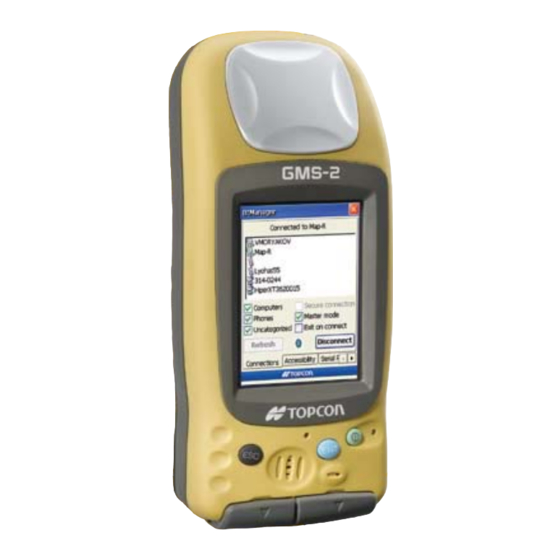
Connecting the GMS-2 with Other Devices Connecting the GMS-2 and a Bluetooth Device BTManager is a utility that connects the GMS-2 with available Bluetooth devices for communication purposes. BTManager manages and controls the Bluetooth module inside the GMS-2. 1. If needed, check the device to ensure Bluetooth communication is supported. - Page 42 Using the GMS-2 Figure 3-4. Check Bluetooth Module Accessibility Settings 4. If using a Phone device (Serial Port tab) or Dial-up network service (Dial-Up tab), select “Enable Service” and the port to use for communication (typically COM1). Selecting one device/service disables the parameters for the other.
- Page 43 Connecting the GMS-2 with Other Devices 6. To close BTManager but remain connected to the internal GMS-2 Bluetooth module, select “Exit on connect”. This allows other programs to open and use the port for communicating with other Bluetooth-enabled devices. If “Exit on connect” is unchecked and BTManager...
-
Page 44: Surveying With The Gms-2
Figure 3-7. Connected to Device and Device Properties Surveying with the GMS-2 The GMS-2 can be used in many surveying situations. From GIS surveying to data collection on a construction jobsite, the GMS-2 provides an integrated solution for all your needs. -
Page 45: Surveying With The Gms-2 And An External Antenna
Connect GMS-2 and External GPS Antenna Figure 3-8. GMS-2 and PG-A5 Antenna Setup 4. Configure the GMS-2 receiver for data collection as described in the corresponding software manual. For example, if using TopPAD as the data collection software, refer to the TopPAD Reference Manual. -
Page 46: Surveying With The Gms-2 And A Beacon Receiver
3-3. In BTManager, the BR-1 would be considered an “Uncategorized” device. Connect GMS-2 and BR-1 Receiver via Bluetooth Figure 3-9. GMS-2 and BR-1 Setup 4. Configure the GMS-2 for data collection as described in the corresponding software manual. Ensure the survey configuration is for an external NOTICE receiver. -
Page 47: Surveying With The Gms-2 And An External Gps Receiver
Connect GMS-2 and GPS Receiver via Bluetooth Figure 3-10. GMS-2 and HiPer Series Receiver Setup (Using Bluetooth) 4. Configure the GMS-2 for data collection as described in the corresponding software manual. Ensure the survey configuration is for an external NOTICE receiver. -
Page 48: Backing Up Windows Ce Ram Data
Performing a regular backup of this data will ensure efficient and continued use of the GMS-2. RAM data will be lost in the following situations: • Losing battery power through draining the battery or removing the battery. -
Page 49: Chapter 4 Troubleshooting
• Check all power sources for drained batteries or incorrectly connected batteries/cables. • Check that the most current software is downloaded onto the GMS-2 and that the most current firmware is loaded into the receiver. Check the TPS website for the latest updates. Then, try the following: •... -
Page 50: Troubleshooting Quick List
To reset the software, see “Resetting the Software” on page 4-3. To reset the hardware, see “Resetting the Hardware” on page 4-4. For power problems: If “The GMS-2 does not power up.” see page 4-5. For general GMS-2 problems: If “The GMS-2 is not receiving data (corrections) from an external receiver.”... -
Page 51: Resetting The Software
Resetting the Software Resetting the Software Only perform a software reset in the following instances: • To quit all active applications. • After installing new applications. • When an application is unresponsive. To perform a software reset, use the stylus to push in the software reset button (Figure 4-1). -
Page 52: Resetting The Hardware
Troubleshooting Resetting the Hardware Only perform a hardware reset when the GMS-2 has become completely unresponsive. A hardware reset will revert all settings to defaults and erase all RAM data. A hardware reset will erase all RAM data and applications. -
Page 53: Charging/Powering Problems
The GMS-2 does not power up. The batteries may be discharged. • Connect the GMS-2 to a grounded outlet to charge the battery. See “Charging the Battery” on page 2-2. • Insert a fully charged battery. See “Installing the Battery” on page 2-4. -
Page 54: Bluetooth Problems
• Allow other device to connect • All devices • Other devices can discover me The GMS-2 is no longer connected via Bluetooth. Check the Bluetooth LED. The LED will be blue when a connection has been established. Cannot connect to a serial port device. -
Page 55: Obtaining Technical Support
To contact TPS Customer Support via e-mail, use one of the following electronic mail addresses (Table 4-1). Table 4-1. Technical Support E-mail For Questions Related To... Use... Hardware (receivers, antennas, firmware) hardware@topcon.com GPS+ and 3DMC psg@topcon.com options@topcon.com rtk@topcon.com P/N 7010-0752... -
Page 56: Website
Website The Topcon Positioning Systems website provides current information about Topcon’s line of products. The support area of the website provides access to frequently asked questions, configuration procedures, manuals, e-mail support, etc. -
Page 57: Gms-2 Software Reference
• Red – no connection, or establishing a connection, between BTManager and the internal Bluetooth module. • White – a connection between BTManager and the internal Bluetooth module has been established. • Green – a connection between the GMS-2 and an external, Bluetooth-enabled device has been established. Bluetooth Indicator Figure A-1. - Page 58 The Connections tab searches for and displays available Bluetooth devices. Once the desired device is selected, it can be connected to. Accessibility The Accessibility tab defines device information (the internal GMS-2 Bluetooth module) and if external devices can see/connect to the GMS-2. GMS-2 Operator’s Manual...
- Page 59 BTManager Table A-1. BTManager Screens (Continued) Description Screen Serial Port and Dial-Up The Serial Port tab enables serial port profile services on the Bluetooth module and selects the internal port to use for Bluetooth communication. The Dial-Up tab enables dial-up network profile service on the Bluetooth module and selects the internal port to use for Bluetooth communication.
-
Page 60: Working With Btmanager
1. Open BTManager and tap the Accessibility tab. 2. Enter a name for the internal GMS-2 Bluetooth module. This name will be used to identify the GMS-2 to other Bluetooth- enabled devices. 3. If pairing the GMS-2 with other devices, enter a PIN code. -
Page 61: Enable Serial Port/Dial-Up Services
BTManager Enable Serial Port/Dial-up Services The Serial Port and Dial-up tabs enable parameters for connecting to computer/network systems. • Serial port service is required to connect to a computer. • Dial-up service is required to connect to a phone. Settings for Serial Port service are only available if Dial-Up service is disabled, and vice versa. -
Page 62: Connect To A Bluetooth Device
GMS-2 Software Reference Connect to a Bluetooth Device The Connections tab searches for and displays Bluetooth devices within range of the GMS-2. Tapping on a device also displays information about the device. 1. Open BTManager. If needed, see the following sections for changing accessibility and/or device connection parameters: •... - Page 63 BTManager 5. If desired, select “Exit on connect” to close BTManager but remain connected to the internal GMS-2 Bluetooth module. This allows other programs to open and use the port for communicating with other Bluetooth-enabled devices. If “Exit on connect” is unchecked and BTManager...
-
Page 64: Resetting The Bluetooth Module
• If a device connection takes more than a couple of minutes. • If a device cannot be found or the Bluetooth module is not responding. To reset the internal GMS-2 Bluetooth module, open BTManager. Once a connection to the module has been established, tap Reset on the Accessibility tab. -
Page 65: Gms Tools
GMS Tools GMS Tools GMS Tools is a simple utility that manages the camera, compass, and receiver board settings in the GMS-2. Getting Acquainted Table A-2 summarizes the screens and settings in GMS Tools. Table A-2. GMS Tools Screens Description... -
Page 66: Working With Gms Tools
GMS-2 Software Reference Table A-2. GMS Tools Screens (Continued) Description Screen GNSS The GNSS tab selects the antenna (internal or external), logging interval, and elevation mask. This tab also displays current position and satellite information. Info The Info tab displays version and copyright information for GMS Tools. - Page 67 GMS Tools • Time of day – select “day” for images captured taken in bright light, “night” for images captured in low light, or “auto” to have the setting automatically detect the ambient light. • Capture size – select the size of the image to capture, in bits. Figure A-7.
-
Page 68: Using The Compass
When calibrating the compass, the new calibration is only used until the GMS-2 is turned off. When the unit is turned on, the default calibration will be used. 1. To calibrate the compass, tap Calibration on the Compass tab. -
Page 69: Viewing Gnss Information And Logging Data
Solution, Autonomous, or Code Differential), the number of satellites being tracked, current time, current position (Lat/Lon/ Alt), and current PDOP. • Antenna – selects the type of GPS antenna used, either the internal GMS-2 antenna or an external antenna. P/N 7010-0752 A-13... -
Page 70: Position Information
GMS-2 Software Reference • Interval – the time interval for recording data. For example, selecting 10 will record a position every 10 minutes. • Elevation – the elevation mask for recording data from satellites above the selected elevation (angle). For example, selecting 10 will have GMS Tools only record data from satellites that are 10°... -
Page 71: Appendix B Specifications
Appendix B Specifications This TPS product is a 50-channel GPS receiver integrated with an internal computer and Windows CE operating system with touch screen, a digital camera, a Bluetooth® wireless technology module, an electronic compass, and an SD card slot. The portable design and product integration allows this device to be a fully-functional, productive tool at any job. -
Page 72: Gms-2 Specifications
Specifications GMS-2 Specifications The following sections provide specifications for the GMS-2 and its internal components. General Details Table B-1 table lists the receiver’s general specifications. Table B-1. GMS-2 General Specifications Physical Enclosure Color Topcon Yellow and Topcon Grey Dimensions W:90 x H:197 x D:46 mm Weight 0.7 kg... - Page 73 GMS-2 Specifications Table B-1. GMS-2 General Specifications (Continued) Power Internal battery Li-ion, 2200 mAh, 7.4 V; repeatable Operating time No less than 7 hours External power 1 port Input voltage 8 to 15 V DC (for work) 10 to 15 V DC (for charge battery) Consumption 2.1 W (with WinCE and GPS receiver turned on)
- Page 74 Specifications Table B-1. GMS-2 General Specifications (Continued) Bluetooth Version: Bluetooth standard 1.2; Class 2; Profile: SPP, Version 1.1 Windows CE Processor Intel PXA270 Processor speed 520MHz Operating System Microsoft Windows CE 5.0 Digital Camera Pixel 1.3M (SXGA...1280x960) Sensor element 1/4 inches color C-MOS sensor...
-
Page 75: Gps Details
GMS-2 Specifications GPS Details Table B-2 lists the GPS board’s general specifications. Table B-2. GPS Board Specifications Tracking Specifications Tracked Signals GPS/GLONASS, L1 C/A Code & Carrier WAAS/EGNOS/MSAS Receiver Type G – GPS L1 GG – GPS/GLONASS L1 Standard Channels Cold Start <... -
Page 76: Connector Specifications
Specifications Connector Specifications The GMS-2 has one antenna connector for radio transmission/ reception and three port connectors for power and data upload/ download. Serial Connector The serial connector (Figure B-1) is a sealed receptacle, 5 pin, port. This connector is configured as port A of the internal GPS receiver. -
Page 77: Usb Connector
Connector Specifications USB Connector Rimmed in yellow, the USB connector is a sealed receptacle, 4 pin TPS cable connector (Figure B-2). Figure B-2. USB Connector for GGD Options Table B-4 gives the USB connector specifications. Table B-4. USB Specifications Number Signal Name Details Bus power input... - Page 78 Specifications Notes: GMS-2 Operator’s Manual...
-
Page 79: Appendix C Safety Warnings
Appendix C Safety Warnings General Warnings TPS receivers are designed for survey and survey related uses (that is, surveying coordinates, WARNING distances, angles and depths, and recording such measurements). This product should never be used: • Without the user thoroughly understanding this manual. -
Page 80: Usage Warnings
The owner should periodically test this product to ensure it provides accurate measurements. Inform TPS immediately if this product does not function properly. Only allow authorized TPS warranty service centers CAUTION to service or repair this product. GMS-2 Operator’s Manual... -
Page 81: Regulatory Information
Appendix D Regulatory Information The following sections provide information on this product’s compliance with government regulations for use. FCC Compliance This device complies with Part 15 of the FCC rules. Operation is subject to the following two conditions: 1. This device may not cause harmful interference, and 2. -
Page 82: Canadian Emission Labeling Requirements
Cet appareil numérique de la classe B respecte conform a la norme NMB-003 du Canada. Community of Europe Compliance The product described in this manual is in compliance with the R&TTE and EMC directives from the European Community. GMS-2 Operator’s Manual... -
Page 83: Weee Directive
WEEE Directive WEEE Directive Following information is for EU-member states only: The use of the symbol indicates that this product may not be treated as household waste. By ensuring this product is disposed of correctly, you will help prevent potential negative consequences for the environment and human health, which could otherwise be caused by inappropriate waste handling of this product. - Page 84 Regulatory Information Notes: GMS-2 Operator’s Manual...
-
Page 85: Appendix E Warranty Terms
1. The warranty against defects in a Topcon battery, charger, or cable is 90 days. P/N 7010-0752... - Page 86 Warranty Terms Notes: GMS-2 Operator’s Manual...
- Page 87 Index Index 3-3–3-5 Bluetooth, connect devices BT-62Q battery 1-12, 2-2 AC/DC converter See also Battery ActiveSync 1-13, 3-3, A-1–A-8 BTManager connecting using Bluetooth indicator install exit notice no partnership 3-4, A-5 serial port 1-12 Antenna, external See also External antenna 1-12 Cables Calibrate...
- Page 88 1-10, B-6 port A 1-13, 2-7 Software 1-11, 4-3 Software reset Bluetooth Start menu, and ENT button 1-9, 2-2 1-10 charging Stylus A-14 3-6–3-9 Log data Surveying with Beacon receiver with external antenna with external receiver GMS-2 Operator’s Manual Index...
- Page 89 Index Test Touch screen calibrate 1-10, B-3 USB port connecting with computer Warnings battery pack general usage 2-4, 3-10 Windows CE RAM P/N 7010-0752 Index...
- Page 90 Notes: GMS-2 Operator’s Manual Index...
- Page 92 Topcon Positioning Systems, Inc. 7400 National Drive, Livermore, CA 94551 Phone: 800-443-4567 www.topcon.com ©2006 Topcon Positioning Systems, Inc. All rights reserved. No unauthorized duplication. GMS-2 Operator’s Manual P/N: 7010-0752 Rev. A Printed in U.S.A. 04/06 250...
Need help?
Do you have a question about the GMS-2 and is the answer not in the manual?
Questions and answers