Table of Contents
Advertisement
Quick Links
Advertisement
Table of Contents

Related Manuals for Topcon HiPer Plus


Summary of Contents for Topcon HiPer Plus
- Page 1 PRECISION GPS+: HiPer+ HiPer Operator’s Manual...
- Page 3 Rev A ©Copyright Topcon Positioning Systems, Inc. April, 2003 All contents in this manual are copyrighted by Topcon. All rights reserved. The information contained herein may not be used, accessed, copied, stored, displayed, sold, modified, published, or distributed, or otherwise reproduced without...
-
Page 5: Table Of Contents
able of Contents Preface ............... xi Terms and Conditions..........xi Regulatory Information ..........xiv Manual Conventions........... xvi Chapter 1 Introduction ............1-1 Overview ..............1-1 Principles of Operation ..........1-2 GPS Overview ............. 1-2 Calculating Positions ........1-3 GPS Positioning ..........1-4 Conclusion ............ - Page 6 Collecting Almanacs ..........2-49 Chapter 3 Setup and Survey ..........3-1 HiPer+ Receiver Setup ..........3-1 Set up HiPer+ Receiver ........3-2 Measure Antenna Height ........3-2 Collect Data ............3-4 Surveying with the HiPer+ ........3-5 Topcon HiPer+ Operator’s Manual...
- Page 7 Table of Contents Static Survey ............3-5 Kinematic Survey ..........3-9 Stop and Go Survey ........3-9 Kinematic Continuous ........3-11 Real-time Kinematic Survey ....... 3-12 Setting up an RTK Base Station ....3-12 Setting up an RTK Rover ......3-17 Chapter 4 Operation ............
- Page 8 USB Connector ........... B-13 Appendix C Safety Warnings ..........C-1 General Warnings ............C-1 Internal Battery Pack Warnings ......... C-2 Usage Warnings ............C-3 Appendix D UHF Radio Usage ..........D-1 Appendix E Warranty Terms ..........E-1 Index Topcon HiPer+ Operator’s Manual...
- Page 9 ist of Figures Chapter 1 Introduction ............1-1 HiPer+ Receiver ............1-1 HiPer+ Radome ............. 1-14 HiPer+ Front Panel ............1-15 HiPer+ Back Panel ............1-16 Chapter 2 Configuration ............ 2-1 PC-CDU Main Screen ........... 2-8 Click File->Connect ............2-8 Bluetooth and RS232 Connection Parameters ....
- Page 10 BTCONF Serial Interface Tab ........2-48 Click Disconnect then Exit ........... 2-48 Chapter 3 Setup and Survey ..........3-1 HiPer+ Antenna Offsets ..........3-3 Configuration->Receiver->MINTER ......3-7 Advanced->Multipath ........... 3-8 Advanced->Loop Management ........3-8 Rover MINTER Configuration ........3-9 Topcon HiPer+ Operator’s Manual...
- Page 11 List of Figures Legacy-E Base Station Setup ........3-13 Set All Parameters to Defaults ........3-14 Receiver Configuration – Positioning ......3-14 Base Tab Configuration ..........3-15 Base Configuration – Ports ........... 3-16 HiPer+ Rover Station Setup .......... 3-18 Rover Tab Configuration ..........3-19 Rover Configuration –...
- Page 12 List of Figures Program Tab Settings ........... 4-28 Bluetooth Firmware Load Complete ......4-28 Appendix B Specifications ............ B-1 Power Connector ............B-11 RS232 Connector ............B-12 USB Connector ............. B-13 viii Topcon HiPer+ Operator’s Manual...
- Page 13 ist of Tables Chapter 1 Introduction ............1-1 Euro Card Options ............1-13 Chapter 2 Configuration ............ 2-1 Data Recording Parameter Behavior ......2-29 Chapter 3 Setup and Survey ..........3-1 HiPer+ Antenna Offset Measurements ......3-3 Chapter 4 Operation ............4-1 FN Key Functions and REC LED Status ......
- Page 14 List of Tables Spread Spectrum/GSM Modem Connector Specifications ........... B-10 Power Connector Specifications ........B-11 RS232 Connector Specifications ........B-12 USB Connector Specifications ........B-13 Topcon HiPer+ Operator’s Manual...
-
Page 15: Preface
Thank you for purchasing this Topcon product. The materials available in this Manual (the “Manual”) have been prepared by Topcon Positioning Systems, Inc. (“TPS”) for owners of Topcon products. It is designed to assist owners with the use of the HiPer+ and its use is subject to these terms and conditions (the “Terms and Conditions”). - Page 16 Windows® is a registered trademark of Microsoft Corporation. Bluetooth™ is a trademark owned by Bluetooth SIG, Inc. and is used by Topcon Positioning Systems, Inc. under license. Other product and company names mentioned herein may be trademarks of their respective owners.
- Page 17 Terms and Conditions PERSON OR ENTITY IN EXCESS OF THE PURCHASE PRICE FOR THE HIPER+. LICENSE AGREEMENT – Use of any computer programs or software supplied by TPS or downloaded from a TPS website (the “Software”) in connection with the HiPer+ constitutes acceptance of these Terms and Conditions in this Manual and an agreement to abide by these Terms and Conditions.
-
Page 18: Regulatory Information
This equipment has been tested and found to comply with the limits for a Class B digital device, pursuant to Part 15 of the FCC rules. These limits are designed to provide reasonable protection against harmful interference in residential Topcon HiPer+ Operator’s Manual... - Page 19 Regulatory Information installations. This equipment generates, uses, and can radiate radio frequency energy, and if not installed and used in accordance with the instructions, may cause harmful interference to radio communications. However, there is no guarantee that interference will not occur in a particular installation.
-
Page 20: Manual Conventions
Supplementary information that can have an affect on system operation, system performance, measurements, or personal safety. CAUTION Notification that an action has the potential to adversely affect system operation, system performance, data integrity, or personal health. Topcon HiPer+ Operator’s Manual... - Page 21 Manual Conventions WARNING Notification that an action will result in system damage, loss of data, loss of warranty, or personal injury. ANGER NDER NO CIRCUMSTANCES SHOULD THIS ACTION BE PERFORMED xvii 1-866-4TOPCON www.topconpositioning.com...
- Page 22 Preface Notes: xviii Topcon HiPer+ Operator’s Manual...
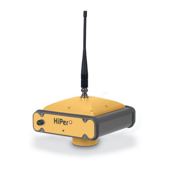
- Page 23 • The Option Authorized File (OAF) Figure 1-1. HiPer+ Receiver Overview Topcon Positioning System’s HiPer+ is a dual-frequency, GPS+ receiver built to be the most advanced and compact receiver for the surveying market. The HiPer+ is a multi-function, multi- purpose receiver intended for precision markets. Precision...
-
Page 24: Chapter 1 Introduction
States Department of Defense (DoD), is a network of up to 28 satellites (at time of printing) orbiting the earth every 12 hours. The Global Navigation Satellite System (GLONASS), is the Russian Federation Ministry of Defense counterpart to Topcon HiPer+ Operator’s Manual... -
Page 25: Calculating Positions
Principles of Operation GPS. At any one time, with a standard 15 degree angle, up to 10 or 12 GPS satellites are visible from any point on earth. When a receiver can also track GLONASS satellites, between 10 and 16 satellites are visible. The GPS and GLONASS network has three components: •... -
Page 26: Gps Positioning
GPS signals. –The more satellites in view, the stronger the signal, the lower the DOP number, providing more accurate positioning. • Availability – The availability of satellites affects the calculation of valid positions. The more visible Topcon HiPer+ Operator’s Manual... -
Page 27: Conclusion
–Several algorithms to detect and correct faulty information. Conclusion Surveyors can use Topcon GPS+ receivers to collect data from a network of satellites and control stations to triangulate precise points anywhere on Earth. This overview simply outlines the basics of GPS and GLONASS positioning. -
Page 28: Chapter 1 Introduction
• Co-Op Tracking • Multipath reduction • Wide area augmentation system (WAAS) • Adjustable phase locked loop (PLL) and delay lock loop (DLL) parameters • Dual-frequency static, kinematic, real-time kinematic (RTK), and differential GPS (DGPS) survey modes Topcon HiPer+ Operator’s Manual... -
Page 29: Standard Package Contents
• Legacy-E GPS receiver • LegAnt-2 flat ground plane antenna • UHF Base radio kit • LitePole • Tripod, tribrach, and adapter • Pinnacle or Topcon Tools software • Cables and cords • Literature Cables Standard package cables include: • Receiver-to-computer RS232 serial cable •... -
Page 30: Software
The following software will also be useful for operating, caring for and using your HiPer+ receiver, and may be required for some applications. • FLoader – Topcon’s firmware loader; available on the Topcon website. • PDLCONF from Pacific Crest – radio configuration program included with Base station package;... -
Page 31: Literature
Li-Ion batteries, a Bluetooth™ wireless technology module, and two Euro cards. One of those cards is the GPS+ 1. Bluetooth is a trademark owned by Bluetooth SIG, Inc. and is used by Topcon Positioning Systems, Inc. under license. 1-866-4TOPCON www.topconpositioning.com... -
Page 32: Internal Components
Radio Modem The HiPer+ incorporates an internal modem for receiving 1-10 data from a Base station. The Base station’s modem transmits the carrier phase and code measurements along Topcon HiPer+ Operator’s Manual... - Page 33 Getting Acquainted with the reference station information (i.e., location and description) to the rover modem. Your HiPer+ may be equipped with one of the following communication boards (however, your receiver may also be configured without a radio/modem): • UHF modem – a Pacific Crest PDL (Positioning Data Link) modem;...
-
Page 34: Power Board
GPS receiver board and power board must be loaded with firmware from the same package. GPS+ receiver board The HiPer+ is supplied with a Euro-112 card capable of processing GPS L1/L2 and GLONASS L1/L2 signals. 1-12 Topcon HiPer+ Operator’s Manual... -
Page 35: Batteries
Getting Acquainted Table 1-1 lists the options available for this card. Table 1-1. Euro Card Options Euro Card Model Available Options Euro-112 (HE_GGD) G: GPS L1 GD: GPS L1/L2 GG: GPS/GLONASS L1 GGD: GPS/GLONASS L1/L2 A WAAS-enabled TPS receiver allows simultaneous tracking of two WAAS satellites. -
Page 36: External Components
This is a BNC female connector for Pacific Crest PDL (UHF) modems, or a TNC female connector for spread spectrum and GSM modems. Bottom Panel • Receiver serial number 1-14 • Receiver part number • Antenna Reference Point (ARP) Topcon HiPer+ Operator’s Manual... -
Page 37: Front Panel
Getting Acquainted Front Panel Figure 1-3 shows the front panel components. MINTER Reset USB Power Figure 1-3. HiPer+ Front Panel • MINTER – The Minimum INTERface for the HiPer+ receiver. The MINTER consists of two keys and four, three-color LEDs. See “Using the MINTER”... -
Page 38: Back Panel
Figure 1-4 shows the back panel components. Vent Plug Slant Height Measure Mark Figure 1-4. HiPer+ Back Panel • Vent plug – Equalizes the pressure between the 1-16 inside of the receiver and the outside environment. • Slant height measure mark (SHMM) Topcon HiPer+ Operator’s Manual... -
Page 39: Option Authorized File (Oaf)
Option Authorized File (OAF) Option Authorized File (OAF) Topcon Positioning Systems issues an Option Authorized File (OAF) to enable the specific options that customers purchase. An Option Authorized File allows customers to customize and configure the HiPer+ according to particular needs, thus only purchasing those options needed. - Page 40 Introduction Notes: 1-18 Topcon HiPer+ Operator’s Manual...
-
Page 41: Configuration
Chapter 2 onfiguration This chapter describes: • HiPer+ power supply • Connecting the receiver and a computer • HiPer+ configuration • Minimum INTERface (MINTER) configuration • Radio configuration • Bluetooth module configuration • Collecting almanacs Before you can use your HiPer+ receiver, you need to: 1. -
Page 42: Powering The Hiper
The speed of the charge depends on the Power and Charger settings on the PC-CDU Receiver Configuration screen, and whether the receiver is turned off or on. See “Power Management” on page 2-15 for more information on these settings. Topcon HiPer+ Operator’s Manual... -
Page 43: External Batteries
Powering the HiPer+ The Li-Ion batteries used in the HiPer+ should run at no less than 98% capacity after 500 charging cycles. These batteries do not need to be drained before recharging. External Batteries In addition to the internal batteries, you can use your HiPer+ with external batteries. -
Page 44: Battery Charger
To turn Off the receiver, press the green power key for more than one and less than four seconds (until both the STAT and the REC LEDs turn off). This delay (about 1 second) will prevent the receiver from being turned off by mistake. Topcon HiPer+ Operator’s Manual... -
Page 45: Connecting The Hiper+ And A Computer
Connecting the HiPer+ and a Computer Connecting the HiPer+ and a Computer To configure, manage files, or maintain the HiPer+, you need to connect the receiver and a computer using: • The HiPer+, a Bluetooth-enabled external device (computer), and PC-CDU. •... - Page 46 1. Connect your receiver and a computer using an RS232 cable (see “Establishing an RS232 Cable Connection” on page 2-7). 2. Click Configuration->Receiver->General. 3. In the Turn on/off Slots area, ensure the Slot 3 (B) check box is enabled. Topcon HiPer+ Operator’s Manual...
-
Page 47: Establishing An Rs232 Cable Connection
3. Continue with Step 1 in “Establishing a PC-CDU Connection” on page 2-7. Establishing a USB Cable Connection Make sure you have installed Topcon’s USB driver (available from http://www.topcongps.com/software/updates.html) before continuing. 1. Using the USB cable, connect the USB port on the receiver to a USB port on the computer. -
Page 48: Pc-Cdu Main Screen
• Set the Connection mode (Direct). • Set the port for your computer (typically COM1) from the Port drop-down list. • Set the communication rate between the receiver and the computer (usually 115200) from the Baud rate drop- down list. Topcon HiPer+ Operator’s Manual... - Page 49 Connecting the HiPer+ and a Computer Figure 2-3. Bluetooth and RS232 Connection Parameters Select the following parameters for USB connections (Figure 2-4) and click Connect: • Set the Connection mode (Direct). • Set the port for your computer (USB) from the Port drop-down list.
-
Page 50: Hiper+ Configuration
Refer to the PC-CDU User’s Manual to manage all possible HiPer+ receiver configurations. The following configuration is recommended for the most common applications. However, you can select configuration parameters as needed for your particular jobsite. 2-10 Topcon HiPer+ Operator’s Manual... -
Page 51: Receiver Configuration
HiPer+ Configuration NOTICE Click Apply after making any configuration change, otherwise your receiver will not accept the change. 1. Connect your receiver and computer. See “Connecting the HiPer+ and a Computer” on page 2-5 for this procedure. 2. Once connected, click on Configuration->Receiver (Figure 2-6). -
Page 52: Receiver Configuration - Minter Tab
If your jobsite is in an area that has obstructions (buildings, trees, etc.), and/or the antenna location is near reflective objects, configure the receiver to reduce errors from these sources. WARNING Do not make other changes without consulting the PC-CDU User’s Manual. 2-12 Topcon HiPer+ Operator’s Manual... -
Page 53: Receiver Configuration - Advanced Tab
HiPer+ Configuration 4. Click the Advanced tab on the Receiver Configuration screen (Figure 2-9). Figure 2-9. Receiver Configuration – Advanced Tab 5. Click the Multipath Reduction tab, enable the following boxes, and click Apply (Figure 2-10). • Code multipath reduction •... -
Page 54: Advanced Configuration - Loop Management
• Static Mode Figure 2-11. Advanced Configuration – Loop Management 7. Click OK to close the Receiver Configuration screen. 8. Click on File->Disconnect, then File->Exit to quit PC-CDU (Figure 2-12). Figure 2-12. Click Disconnect then Exit 2-14 Topcon HiPer+ Operator’s Manual... -
Page 55: Power Management
PC-CDU or clearing the NVRAM. Power Management You can use Topcon’s PC-CDU software to manage your receiver’s power. The complete description of PC-CDU exceeds the scope of this manual, but can be found in the PC-CDU User’s Manual. - Page 56 • Battery A – receiver will consume power from battery A. • Battery B – receiver will consume power from battery B. • External – receiver will use an external power supply. 2-16 Topcon HiPer+ Operator’s Manual...
- Page 57 HiPer+ Configuration 4. Select the Charger Mode drop-down list to set the desired charger mode (Figure 2-15). Current Mode displays the charging battery: a, b, or none (off). Figure 2-15. Select Charger Mode • Off – receiver will not charge batteries. •...
-
Page 58: Select Power Output Modes - Ports
• Off – the power will be absent even if the receiver is turned on. • Always – the power board will deliver voltage on pin one of all serial port connectors even if the receiver is turned off. 2-18 Topcon HiPer+ Operator’s Manual... -
Page 59: Select Power Output Modes - Slots
HiPer+ Configuration 6. Select the Power output modes Slots drop-down list to set power output on internal slots (Figure 2-17). Figure 2-17. Select Power Output Modes – Slots • On – all slots are powered if the receiver is turned on. •... -
Page 60: Enable And Apply Power Settings
(Figure 2-19). 9. Select and check the Enable Low Power Mode check box to put the receiver’s processor into low power consumption mode (Figure 2-19). Figure 2-19. Enable and Apply Power Settings 10. Click Apply. 2-20 Topcon HiPer+ Operator’s Manual... -
Page 61: Charging Internal Batteries
HiPer+ Configuration Charging Internal Batteries Use one of the following conditions for maximum battery charge speed. • The receiver is turned off. Power Mode and Charger Mode are set to Auto. See “Power Management” on page 2-15 for setting these parameters. •... -
Page 62: Checking Internal Battery Status
(Power and FN) and four LEDs (STAT, REC, BATT, and RX) that control and display the receiver’s operation (Figure 2-20). Power key Reset Key BATT (battery LED) STAT (status LED) 2-22 REC (recording LED) RX (modem LED) FN key (function/recording) Figure 2-20. HiPer+ MINTER Topcon HiPer+ Operator’s Manual... - Page 63 MINTER Configuration The MINTER allows the user to perform numerous functions: • Turn the receiver on or off, put it in Sleep mode or Zero power mode. • Turn data recording on or off (FN key). • Change the receiver’s information mode. •...
-
Page 64: Configuration->Receiver
• Files Creation mode on page 2-26 • Automatic File Rotation Mode (AFRM) on page 2-26 • FN key mode on page 2-28 2-24 • Initial data collection dynamic mode on page 2-28 • Data recording auto-start on page 2-28 Topcon HiPer+ Operator’s Manual... -
Page 65: Receiver Configuration - Minter Tab
MINTER Configuration Figure 2-23. Receiver Configuration – MINTER Tab Recording Interval parameter This parameter specifies the message output interval into the log file when the MINTER FN key (pressed for 1–5 seconds) activates data logging. This setting is used not only when logging a single log file, but also when logging receiver data in AFRM mode. - Page 66 When opening a new log file, the receiver enables the default set of messages outputted with the default output period. 2-26 Both the default set of messages and the default output period are programmable. Topcon HiPer+ Operator’s Manual...
- Page 67 MINTER Configuration • Period – specifies the time duration of each log file created in AFRM mode. Values are 60 to 86400 seconds. The default value is 3600 seconds. • Phase – specifies the “phase” (constant time shift) of creating multiple log files in AFRM mode.
- Page 68 Table 2-1 gives the different scenarios available and the results after power is restored to the receiver. “Specified file” 2-28 refers to the file name entered in the Always append to file parameter. Topcon HiPer+ Operator’s Manual...
-
Page 69: Data Recording Parameter Behavior
MINTER Configuration Table 2-1. Data Recording Parameter Behavior Enabled Radio Button Results Before Power Failure Always Data logging will Receiver will Receiver will Receiver not resume when resume data resume data data logged power is restored. logging to the logging to the to file same file when same file when... -
Page 70: Radio Configuration
PC and proceed with the radio configuration. 1. Connect your receiver and computer. See “Connecting the HiPer+ and a Computer” on page 2-5 for this procedure. Use a 38400 baud rate. 2-30 Topcon HiPer+ Operator’s Manual... -
Page 71: File->Manual Mode
Radio Configuration 2. Once connected, click on File->Manual Mode to create a daisy chain between the receiver’s port (A or D) and the HiPer+ PDL modem (Figure 2-24). Figure 2-24. File->Manual Mode 3. Type each of the following commands, pressing Enter (or clicking Send command) after each command. -
Page 72: Manual Mode - Command Responses
5. Run the PDL Radio Configuration Program (pdlconf.exe) from Pacific Crest (Figure 2-26 on page 2-33). Make sure you have the latest version (2.20 or higher). Upgrades for this software are available on the Pacific Crest website (www.paccrst.com/download/ upgrade.htm). 2-32 Topcon HiPer+ Operator’s Manual... -
Page 73: Pdl Radio Configuration Main Screen
Radio Configuration Figure 2-26. PDL Radio Configuration Main Screen 6. Click the Pacific Crest logo in the upper left corner of the main screen (Figure 2-27). Figure 2-27. PDL Top Left Corner Icon Menu 2-33 1-866-4TOPCON www.topconpositioning.com... -
Page 74: Set Capture Method->Soft Break
Configuration 7. From the pop-up menu, click Set Capture Method ->Soft Break (Figure 2-28). Figure 2-28. Set Capture Method->Soft Break 8. Click Load to connect to the radio (Figure 2-29). Figure 2-29. Click Load 2-34 Topcon HiPer+ Operator’s Manual... - Page 75 Radio Configuration 9. On the Identification tab, type Owner information (Figure 2-30). Figure 2-30. PDL Identification Tab The Identification screen supplies current information concerning firmware version, serial number, frequency, and power of the radio modem. 10. Click the Radio Link tab and set the following parameters (Figure 2-31 on page 2-36): •...
- Page 76 11. Click the Serial Interface tab and set the following parameters (Figure 2-32 on page 2-37): • Baud Rate – 38400 • Parity – None NOTICE Parity should always be set to None. • Mode – Transparent w/EOT Timeout 2-36 Topcon HiPer+ Operator’s Manual...
- Page 77 Radio Configuration Figure 2-32. PDL Serial Interface Tab 12. If you made changes, click the Program button on the left of the screen to save them to the modem’s memory (Figure 2-33). Figure 2-33. PDL – Click Program 2-37 1-866-4TOPCON www.topconpositioning.com...
-
Page 78: 15. Click File->Connect
15. Click File->Connect. 16. On the Connection Parameters screen, select a baud rate of 38400 and enable the Manual mode only check box (Figure 2-35), then click Connect. 2-38 Figure 2-35. Connection Parameters – Manual Mode Only Topcon HiPer+ Operator’s Manual... -
Page 79: Manual Mode Command Responses
Radio Configuration 17. On the Manual Mode screen, write the following commands, pressing Enter (or clicking Send command) after each command. When finished, you should have six responses (Figure 2-36). QUIT %%set,cur/term/imode,cmd %%set,dev/ser/c/echo,/dev/null %%set,dev/ser/c/imode,cmd %%set,dev/ser/c/rate,38400 %%set,cur/term/rate,115200 Figure 2-36. Manual Mode Command Responses 18. -
Page 80: Configuring A Gsm Radio Modem
20cm between the user and the GSM radio modem. To access your GSM radio modem, you will need to use Topcon’s FC-1000 external controller and TopSURV. Refer to the TopSURV Reference Manual or the TopSURV User’s Manual for more detailed configuration information. -
Page 81: Select A Survey Configuration
Radio Configuration 3. Click Job->Config->Survey to open the Select Survey Config dialog box (Figure 2-37). Figure 2-37. Select a Survey Configuration 4. From the GPS+ Config drop-down list, select My RTK, or the name of your GPS+ survey configuration, and click the “...”... -
Page 82: Base Or Rover Radio Configuration
Base or Rover (Figure 2-39). 2-42 Figure 2-39. Set Base or Rover Cell Phone Parameters • For the Base radio – If your GSM modem does not require a PIN, leave this field blank. Topcon HiPer+ Operator’s Manual... -
Page 83: Bluetooth Module Configuration
Bluetooth Module Configuration The Base radio is the Slave, only receiving calls from Rover stations, so no phone number to call is required. • For the Rover radio – If your GSM modem does not require a PIN, leave this field blank. The Rover radio is the Master, sending calls to the Base station. -
Page 84: Bluetooth Module Configuration Main Screen
(usually COM1) to the receiver’s serial port A. 2. Press the power buttons on the receiver and computer to turn them on. 3. Run the Bluetooth module configuration program (Btconf.exe) (Figure 2-40). 2-44 Figure 2-40. Bluetooth Module Configuration Main Screen Topcon HiPer+ Operator’s Manual... -
Page 85: Select Communication Port And Click Connect
Bluetooth Module Configuration Notice that the lower left corner shows a “Disconnected” status for the computer and Bluetooth module. For BTCONF version and copyright information, click the About button. 4. From the drop-down list in the upper left corner, select the computer serial port (usually COM1) used for communication (Figure 2-41). -
Page 86: Btconf Identification Tab
The security section allows you to set data security and unauthorized access parameters for the Bluetooth module. 7. Enter up to 14 characters to set a unique name for the Bluetooth module (Figure 2-43), and click Apply. 2-46 Figure 2-43. BTCONF Parameters Tab Topcon HiPer+ Operator’s Manual... -
Page 87: Btconf Security Parameters
Bluetooth Module Configuration 8. To set security parameters (Figure 2-44), enter and enable the following, then click Apply: • Bluetooth PIN – enter up to 16 characters to specify a personal identification number for the Bluetooth module. • Encryption – enable to have the Bluetooth module encrypt wirelessly sent data. -
Page 88: Click Disconnect Then Exit
Bluetooth module replies and corresponding commands on the computer terminal. If needed, click Apply. Figure 2-45. BTCONF Serial Interface Tab 10. Click Disconnect then Exit (Figure 2-46) to quit BTCONF. Figure 2-46. Click Disconnect then Exit 2-48 Topcon HiPer+ Operator’s Manual... -
Page 89: Collecting Almanacs
Collecting Almanacs Collecting Almanacs Each satellite broadcasts a message (almanac) which gives the approximate orbit for itself and all other satellites. If the receiver has an almanac, you can considerably reduce the time needed to search for and lock on to satellite signals. The receiver regularly updates the almanac and stores the most recent almanac in its Non-Volatile Random Access Memory (NVRAM). - Page 90 Configuration Notes: 2-50 Topcon HiPer+ Operator’s Manual...
-
Page 91: Setup And Survey
Chapter 3 etup and Survey This chapter describes: • HiPer+ setup • RTK Base station setup • RTK Rover setup • Basic surveying with the HiPer+ Your HiPer+ can be used as a Rover station or a Base station with an optional external radio. -
Page 92: Set Up Hiper+ Receiver
(ARP) located on the bottom of the receiver at the base of the mounting threads. • Slant – measured from the marker to the lower edge of the antenna slant height measure mark (SHMM) located on both end panels of the receiver. Topcon HiPer+ Operator’s Manual... -
Page 93: Hiper+ Antenna Offsets
HiPer+ Receiver Setup 4. Measure the antenna height above the point or marker. Figure 3-1 illustrates the antenna offsets and Table 3-1 gives the offset measurements. (See Figure 1-3 on page 1-15 and Figure 1-4 on page 1-16 for the exact SHMM location.) SHMM 30.50mm... -
Page 94: Collect Data
10. Release the FN key when the REC (recording) LED light turns green. This indicates that a file has opened and data collection has started. The REC LED blinks each time data is saved to the internal memory. Topcon HiPer+ Operator’s Manual... -
Page 95: Surveying With The Hiper
Surveying with the HiPer+ You can use PC-CDU to configure data logging. See “MINTER Configuration” on page 2-22 or refer to the PC-CDU User’s Manual for more information. 11. When finished, press and hold the FN key until the REC LED light goes out. - Page 96 HiPer+ and a Computer” on page 2-5 for this procedure. 2. Open PC-CDU, click Configuration->Receiver ->MINTER and specify the following parameters, then click Apply (Figure 3-2 on page 3-7): • Recording Interval – 15 seconds Topcon HiPer+ Operator’s Manual...
-
Page 97: Configuration->Receiver->Minter
Surveying with the HiPer+ • Elevation Mask Angle – 15 degrees • File Name Prefix – last 3 digits of receiver serial number • LED blink mode switch – enable to start and stop static data recording using the FN key Figure 3-2. - Page 98 Apply (Figure 3-4): • Enable Co-Op tracking – enable • Static mode – enable Figure 3-4. Advanced->Loop Management 5. Set up each antenna and receiver as described in “HiPer+ Receiver Setup” on page 3-1. 6. Begin your survey. Topcon HiPer+ Operator’s Manual...
-
Page 99: Kinematic Survey
Surveying with the HiPer+ Kinematic Survey You can use the kinematic survey method for either a Stop and go survey or a Kinematic continuous (trajectory) survey. Stop and Go Survey The stationary receiver (Base station) is set up at a known point such as a survey monument, or an unknown point. - Page 100 Turn off the Rover if needed. This method of GPS survey allows the operator to reduce the point occupation time, thus permitting field crews to survey many more points compared to the other methods 3-10 available. Topcon HiPer+ Operator’s Manual...
-
Page 101: Kinematic Continuous
Surveying with the HiPer+ Kinematic Continuous Kinematic continuous surveying, also known as trajectory surveying, allows the Rover to move without having to stand still, record data, move to another point, and do it all again. If the surveyor knows the coordinates of the starting point, the rover will not need to be initialized. -
Page 102: Real-Time Kinematic Survey
2. Connect an external modem to port C for a Legacy-E or port D for the HiPer+. 3. Set up hardware as shown in Figure 3-6 on page 3-13. This setup shows a Legacy-E Base station setup. 3-12 Topcon HiPer+ Operator’s Manual... -
Page 103: Legacy-E Base Station Setup
Surveying with the HiPer+ Figure 3-6. Legacy-E Base Station Setup NOTICE Connect the radio antenna before switching the modem to the transmitting mode. 4. Press the power key on the receiver. 5. Check the STAT light for tracked satellites. 6. Connect your receiver and computer. See “Connecting the HiPer+ and a Computer”on page 2-5 for this procedure. -
Page 104: Receiver Configuration - Positioning
MINTER tab. Specify desired settings. Refer to the PC-CDU User’s Manual for more information. 10. Select the Positioning tab and set the Position Masks, Elevation mask parameter to 15 (Figure 3-8). 3-14 Figure 3-8. Receiver Configuration – Positioning Topcon HiPer+ Operator’s Manual... -
Page 105: Base Tab Configuration
Surveying with the HiPer+ 11. Select the Base tab and set the following parameters (Figure 3-9): • GPS/GLO at one time – enable • Antenna position – enter Lat, Lon, and Alt values. Click Get from receiver. Enable Averaged and enter the Averaged Span in seconds, then click Apply. -
Page 106: Base Configuration – Ports
For Pacific Crest PDL (UHF) modems, use a 38400 baud rate. For Spread Spectrum 915 MHz/2.4 GHz modems, use a 19200 baud rate. Figure 3-10. Base Configuration – Ports 3-16 13. Click Apply. The receiver begins sending data to the selected port. Topcon HiPer+ Operator’s Manual... -
Page 107: Setting Up An Rtk Rover
Surveying with the HiPer+ If using a Pacific Crest PDL (UHF) external modem, follow these steps to configure this modem: 14. When finished with the previous steps, press the power button on the external modem. 15. Select the radio transmission power using the Low/ High toggle on the rear panel of the modem. -
Page 108: Hiper+ Rover Station Setup
“Connecting the HiPer+ and a Computer”on page 2-5 for this procedure. 3. Click Configuration->Receiver. 4. Select the Positioning tab and set the Position Masks, Elevation mask (degrees) parameter to 15 (Figure 3-8 on page 3-14). 3-18 Topcon HiPer+ Operator’s Manual... -
Page 109: Rover Tab Configuration
Surveying with the HiPer+ 5. Select the Rover tab and set the desired Positioning Mode (Figure 3-12). Figure 3-12. Rover Tab Configuration If you selected RTK Float or RTK Fixed, adjust the following RTK Parameters settings: • Select Extrapolation or Delay. –Extrapolation is for low-latency, high frequency output (>= 5 Hz) RTK applications. - Page 110 For Pacific Crest PDL (UHF) modems, use a 38400 baud rate. For Spread Spectrum 915 MHz/2.4 GHz modems, use a 19200 baud rate. 3-20 Topcon HiPer+ Operator’s Manual...
-
Page 111: Pc-Cdu Main Screen
Surveying with the HiPer+ Figure 3-13. Rover Configuration – Ports 7. Click Apply. 8. Click OK to close the Receiver Configuration screen. 9. On the main screen (Figure 3-14), check the LQ field to ensure the receiver obtains differential corrections. Usually, the receiver will start to output the coordinates of the antenna’s phase center along with the solution type within 10–30 seconds. - Page 112 If the receiver is not (for some reason) receiving differential corrections, or if none of the ports has been configured to receive differential corrections, the LQ 3-22 field will either be empty or it will look like this: 100%(999,0000,0000). Topcon HiPer+ Operator’s Manual...
-
Page 113: Operation
• Clearing the NVRAM • Changing receiver modes • Checking and loading firmware Using the MINTER The MINTER (Figure 4-1) is Topcon’s Minimum INTERface used to display and control data input and output. Power key Reset Key BATT (battery LED) -
Page 114: Power Key
During the first second of pressing the FN key, the REC LED is orange. • Pressing the FN key for more than one and less than five seconds will start/stop data recording. Topcon HiPer+ Operator’s Manual... - Page 115 Using the MINTER During data recording the REC LED is green. If the REC LED is red, the receiver has run out of memory, has a hardware problem, or contains an improper OAF (see “Option Authorized File (OAF)” on page 1-17 for more information on OAFs). •...
-
Page 116: Chapter 4 Operation
If FN key mode is “Occupation mode switch” Green Release to start recording (Kinematic or Static post-processing occupation mode) Pressed for 5–8 Release to turn serial port A baud seconds rate to 9600 bps. Pressed for > 8 No light No function. seconds Topcon HiPer+ Operator’s Manual... - Page 117 Using the MINTER Table 4-1. FN Key Functions and REC LED Status FN Key REC LED Status When data recording is on, and the FN key is... No free memory; hardware problem with data recording. If FN key mode is “LED blink mode switch” Green Data recording started (post- processing occupation mode...
-
Page 118: Battery Led
• No light – the modem is off. • Green – the modem is on, but signal reception has not started. • Orange – the modem is receiving a signal. Topcon HiPer+ Operator’s Manual... -
Page 119: Information Modes
Using the MINTER Information Modes The HiPer+ has two information modes: Normal and Extended Information Mode (EIM). Normal In normal mode, the STAT LED indicates the number of tracked satellites and the position’s computation status. Extended Information Mode (EIM) Extended Information Mode is used for receiver testing purposes. -
Page 120: Downloading Files To A Computer
HiPer+. 1. Connect your receiver and computer. See “Connecting the HiPer+ and a Computer” on page 2-5 for this procedure. Enable RTS/CTS handshaking (Figure 4-2 on page 4-9). Topcon HiPer+ Operator’s Manual... -
Page 121: Connection Parameters - Rts/Cts Handshaking
Downloading Files to a Computer Figure 4-2. Connection Parameters – RTS/CTS Handshaking 2. Click File->File Manager (Figure 4-3). Figure 4-3. File->File Manager 1-866-4TOPCON www.topconpositioning.com... -
Page 122: Find Files To Download
6. Select the file(s) you want to download (Figure 4-5 on page 4-11). To select multiple files, hold down the Shift key and click on nonsequential files to select several files at once; or, hold down the Ctrl key and click on individual files. 4-10 Topcon HiPer+ Operator’s Manual... -
Page 123: Download Files
Downloading Files to a Computer Figure 4-5. Download Files 7. Click the Download button. During the download, status indicators display next to each file (Figure 4-6). • Blue indicator – file in queue for downloading. • Red indicator – file currently downloading. •... -
Page 124: Deleting Files
Use the following steps to delete files from your receiver. 1. Connect your receiver and computer. See “Connecting the HiPer+ and a Computer” on page 2-5 for this procedure. Enable RTS/CTS handshaking (Figure 4-8). 4-12 Figure 4-8. Connection Parameters – RTS/CTS Handshaking Topcon HiPer+ Operator’s Manual... -
Page 125: File->Manager
Deleting Files 2. Click File->File Manager (Figure 4-9). Figure 4-9. File->Manager 3. On the Download files tab or Current log files tab, select the file(s) you want to delete (Figure 4-10). To select multiple files, hold down the Shift key and click on nonsequential files to select several files at once;... -
Page 126: Checking An Oaf
Figure 4-11. Click Disconnect then Exit Checking an OAF For a complete list of options and their details, visit the Topcon website. You can check the status of your receiver’s options, and load any new OAF, using the RS232 cable, a computer, and PC-CDU. - Page 127 Checking an OAF The Option Manager screen displays (Figure 4-13 on page 4-16) and contains the following information: • Option name – a name/description of the option • Current – the current status of the option • Purchased – if the option is purchased or not •...
-
Page 128: Option Manager
Operation Figure 4-13. Option Manager 3. When finished, click Exit on the Option Manager screen, then click File->Disconnect to prevent conflicts with serial port management. 4-16 Topcon HiPer+ Operator’s Manual... -
Page 129: Loading An Oaf
Loading an OAF Loading an OAF Topcon Positioning System dealers provide customers with OAF files. For any OAF related questions, E-mail TPS at options@topconps.com. Please have your receiver ID number available (see “Checking Firmware Version” on page 4-21). 1. To load a new OAF, follow steps one and two in “Checking an OAF”... -
Page 130: Managing Hiper+ Memory
(around 15 minutes). 4-18 Clearing the NVRAM of your receiver will not delete any files already recorded in your receiver’s memory. However, it will reset your receiver to factory default values. Topcon HiPer+ Operator’s Manual... -
Page 131: Using Minter To Clear Nvram
Clearing the NVRAM In addition, the NVRAM is used to keep information about the receiver file system. Note that after clearing the NVRAM, the receiver's STAT LED will flash orange for a few seconds indicating that the receiver is scanning and checking the file system. -
Page 132: Changing Receiver Modes
This 4-20 means that if you fully charge your receiver, turn it off and store it, the receiver will drain its battery power in less than two months. To stop the power board and Bluetooth module Topcon HiPer+ Operator’s Manual... -
Page 133: Checking Firmware Version
Checking Firmware Version from draining the batteries, put your receiver in Zero Power Mode. 1. Turn on your receiver. 2. Press and hold the power key for more than 8 seconds, but less than 14 seconds. 3. Release the power key when both LEDs become red. When the LEDs turn off, your receiver will be in Zero Power Mode. -
Page 134: Help->About
TPS or your dealer: • Receiver model • Receiver ID • Firmware version 3. When finished, click OK, then click File->Disconnect to prevent conflicts with serial port management. 4-22 Topcon HiPer+ Operator’s Manual... -
Page 135: Loading New Firmware
Loading New Firmware Loading New Firmware Base and Rover receivers must be loaded with the same firmware version. Use the latest firmware version, available for download from the TPS website, to ensure your receiver has access to the most recent updates. The receiver board and power board must be loaded with firmware from the same package. -
Page 136: Receiver And Power Board Firmware
These files must come from the same firmware package. 1. In FLoader, select the Device tab and set the Device Type as Receiver (Figure 4-19). Figure 4-19. Get Device Type 2. Click Get from Device for device information (Figure 4-19). 4-24 Topcon HiPer+ Operator’s Manual... -
Page 137: Program Tab Settings
Loading New Firmware 3. Select the Program tab and set the Capture Method to Soft Break Capture (recommended) (Figure 4-20). Figure 4-20. Program Tab Settings 4. Browse for and select the receiver board’s RAM file and Flash file (Figure 4-20). 5. -
Page 138: Program Tab Settings
Reselect the correct file. 11. Click File->Exit. 12. Clear the receiver’s NVRAM (see “Clearing the NVRAM” on page 4-18) and update the almanac (see “Collecting Almanacs” on page 2-49) after loading new firmware. 4-26 Topcon HiPer+ Operator’s Manual... -
Page 139: Bluetooth Module Firmware
Loading New Firmware Bluetooth Module Firmware Bluetooth module firmware is released as a compressed file that you download and decompress. This file contains the following two files: • btloader.ldr – the Bluetooth module RAM file • btmain.ldp – the Bluetooth module Flash file NOTICE You must load both files when loading new firmware. -
Page 140: Program Tab Settings
(Figure 4-25). Figure 4-25. Bluetooth Firmware Load Complete NOTICE If you selected an incorrect RAM or Flash file, an error message displays at the bottom of the dialog box. Reselect the correct file. 4-28 6. Click File->Exit. Topcon HiPer+ Operator’s Manual... -
Page 141: Configuration->Receiver
Chapter 5 roubleshooting In general, as long as you follow the maintenance and safety instructions provided in this manual, you should have few problems with your HiPer+. This chapter will help you diagnose and solve some common problems you may encounter with your HiPer+ receiver. -
Page 142: Chapter 5 Troubleshooting
“Powering the HiPer+” on page 2-2. but internal batteries are discharged. The receiver may have If after charging your internal batteries a defective charger or overnight, and your HiPer+ is not defective internal powering, contact TPS Customer batteries. Support for advice. Topcon HiPer+ Operator’s Manual... -
Page 143: Receiver Problems
Receiver Problems Receiver Problems The following are some of the most commonly encountered receiver problems. Problem The receiver cannot establish a connection to a computer or external controller. Causes Solutions The receiver’s Port B 1. Connect your receiver and a has been disabled, computer using an RS232 cable preventing wireless... - Page 144 Problem The receiver tracks too few satellites. Causes Solutions The elevation mask • Lower the elevation mask. value is too high (e.g., • See page 2-25 for information on above 15 degrees). setting the elevation mask. Topcon HiPer+ Operator’s Manual...
-
Page 145: Advanced->Multipath
Receiver Problems The survey is • Check that the Multipath Reduction conducted near boxes have been enabled. obstructions (tree 1. Connect your receiver and a canopy, tall buildings, computer and start PC-CDU. etc.). See “Connecting the HiPer+ and a Computer” on page 2-5. 2. - Page 146 The Base and Rover • Set the Base and Rover receivers to modems are set to the same radio channel. different radio • See “Radio Configuration” on channels. page 2-30. Topcon HiPer+ Operator’s Manual...
- Page 147 Receiver Problems A discrepancy exists Ensure the Base and Rover receivers between the use the same corrections input/output differential standards format: used at the Base and 1. Connect your receiver and a Rover receivers. computer and start PC-CDU. See “Connecting the HiPer+ and a Computer”...
- Page 148 The receiver has • Delete unnecessary files (see already logged 256 “Deleting Files” on page 4-12) files into the internal • Use the AFRM feature. See memory. “Automatic File Rotation Mode (AFRM) parameters” on page 2-26. Topcon HiPer+ Operator’s Manual...
-
Page 149: Bluetooth Problems
Bluetooth Problems Bluetooth Problems The following are some of the most commonly encountered error messages. BTCONF reports the error messages in the status bar. Error Message Can’t find receiver. Causes Solutions The receiver is turned Ensure the receiver has power and is off. - Page 150 2. Click Configuration->Receiver ->General. 3. In the Turn on/off Slots area, enable the Slot 3 (B) check box. The Bluetooth module Close the connection with the device, is linked with another then connect to your receiver. device. 5-10 Topcon HiPer+ Operator’s Manual...
- Page 151 Bluetooth Problems The Bluetooth 1. Put your receiver in Zero Power module’s processor is Mode. See “Zero Power Mode” on overloaded. page 4-20 for details. 2. Press the Reset key for about one second to return the receiver to normal mode. 3.
- Page 152 1. If you changed settings for your settings may have Bluetooth module, remove it from changed. the list of discovered Bluetooth devices using the Bluetooth manager program (supplied with the device used to manage the receiver). 5-12 2. Repeat the search. Topcon HiPer+ Operator’s Manual...
-
Page 153: Creating Scripts
Appendix A reating Scripts Script files allow you to save manual commands into one file. You can then load this single script instead of typing each individual command. Use the following procedure to create script files. For more information on script files, see the PC-CDU User’s Manual. -
Page 154: Creating Scripts
1. Click Load script on the Manual Mode dialog box. 2. Navigate to the folder that contains your script file. 3. Select the appropriate script file and click Open. 4. Press Enter or click Send command to run the script file. Topcon HiPer+ Operator’s Manual... -
Page 155: Specifications
Appendix B pecifications This TPS product is a 40-channel GPS+ (GPS and GLONASS) receiver with an internal antenna, an internal UHF or GSM radio, a Bluetooth wireless technology module, and a rugged aluminum housing complete with MINTER and cable connectors. HiPer+ Specifications Table B-1 lists HiPer+ component details. -
Page 156: Appendix B Specifications
Warm Start < 10 sec Reacquisition < 1 sec Technology Co-Op tracking Low signal tracking Advanced Multipath mitigation WAAS Adjustable PLL and DLL parameters Radio Modem Spread Spectrum Internal 915 MHz or 2.4 GHz Spread Spectrum transceiver Topcon HiPer+ Operator’s Manual... -
Page 157: Hiper+ Specifications
HiPer+ Specifications Table B-1. HiPer+ Specifications Component Details UHF Radio modem Internal Rx or External Tx/Rx GSM modem Europe and Asia – 900/1800 MHz USA and Canada – 900/1900 MHz Bluetooth Module specifications Type Class 2 Service classes Miscellaneous Supported profiles LM, L2CAP, SDP, PPP Frequency Country North America and Europe... -
Page 158: Minter
Battery weight 165 g (1 battery) Number of built-in 2 batteries batteries Change battery non-detachable battery Operating time ~11.5 hours with UHF PDL Radio ON ~13.5 hours with UHF PDL Radio OFF External power 1 port Topcon HiPer+ Operator’s Manual... - Page 159 -30 C° to + 60 C° with batteries temperature Storage temperature -40 C° to +75 C° with batteries Physical Enclosure Aluminum extrusion, rainproof Color Topcon Yellow Dimensions W:158.5 x H:113 x D:173 mm Weight 1.72 kg Antenna Internal Battery Two internal...
- Page 160 1Hz standard; 5, 10, 20Hz optional Output interval for 1Hz standard; 5, 10, 20Hz optional RTCM correction data Elevation mask 0 to 90 deg (independent of data logging Multi-base DGPS Differential correction select mode: Nearest, Mix, Best (optional) Topcon HiPer+ Operator’s Manual...
- Page 161 HiPer+ Specifications Table B-1. HiPer+ Specifications Component Details Correction format CMR2/CMR+ (Trimble compatible), RTCM SC104 Ver 2.2 or 2.3 RTCM message type 3, 18, 19, 20, 21, 22; user selectable Reverse RTK Will be available in future Ambiguity initialize OTF (L1, L1/L2) Baseline Length Up to 50km in the morning and evening.
- Page 162 Co-op tracking loop On/Off, Static Mode, Bandwidth of individual PLL, setting Bandwidth of common PLL Smoothing interval Code and Carrier WAAS/EGNOS Standard Battery Charger (AC Adapter) Size W:60 x L:112 x H:36 mm Weight 235 g Topcon HiPer+ Operator’s Manual...
- Page 163 6 hours for 90% Charge Cinderella days is an option that turns a single frequency, GPS receiver into a dual-frequency, GPS+GLONASS receiver for 24 hours every other Tuesday at GPS midnight. Refer to Topcon’s website for more information and specific Cinderella day dates. NOTICE...
-
Page 164: Connector Specifications
RF input from PDL antenna Spread Spectrum modem (TPS) or GSM modem connector type (Table B-3) is a TNC RF connector. Table B-3. Spread Spectrum/GSM Modem Connector Specifications Type Signal Name Details Modem I/O RF input from modem antenna B-10 Topcon HiPer+ Operator’s Manual... -
Page 165: Power Connector
Connector Specifications Power Connector The power connector (Figure B-1) is a sealed receptacle, 5 pin, ODU part number G80F1C-T05QF00-0000. Figure B-1. Power Connector Table B-4 gives power connector specifications. Table B-4. Power Connector Specifications Number Signal Name Details Power_INP 6 to 28 volts DC input Power_INP 6 to 28 volts DC input Power_GND... -
Page 166: Serial C-Rs232 Connector
Table B-5 gives the RS232 cable connector specifications. Table B-5. RS232 Connector Specifications Number Signal Name Details Power_OUT Power Output (I<0.2 A) Signal ground Clear to send Request to send Receive data Transmit data Not used B-12 Topcon HiPer+ Operator’s Manual... -
Page 167: Usb Connector
Connector Specifications USB Connector The USB connector is a sealed receptacle, 5 pin, ODU part number G80F1C-T05QF00-0000 (Figure B-3). Figure B-3. USB Connector Table B-6 gives the USB connector specifications. Table B-6. USB Connector Specifications Number Signal Name Details Not used USB_PWR Bus power Ground... - Page 168 Specifications Notes: B-14 Topcon HiPer+ Operator’s Manual...
-
Page 169: Safety Warnings
Appendix C afety Warnings General Warnings NOTICE To comply with RF exposure requirements, maintain at least 20cm between the user and the GSM radio modem. WARNING The HiPer+ is designed for survey and survey related uses (i.e., surveying coordinates, distances, angles and depths, and recording such measurements). -
Page 170: Internal Battery Pack Warnings
– Do not attempt to open the battery pack or replace it. – Do not disassemble the battery pack. – Do not charge in conditions different than specified. Topcon HiPer+ Operator’s Manual... -
Page 171: Usage Warnings
Usage Warnings – Do not use other than the specified battery charger. – Do not short circuit. – Do not crush or modify. CAUTION When plugging the power/charger cable into an outlet, use a grounded, main socket outlet. Usage Warnings CAUTION If this product has been dropped, altered, transported or shipped without proper... - Page 172 Safety Warnings Notes: Topcon HiPer+ Operator’s Manual...
-
Page 173: Uhf Radio Usage
Appendix D HF Radio Usage NOTICE Many countries require a license for radio users (such as the United States). Be sure you comply with all local laws while operating a UHF radio. Surveying in RTK mode has made UHF the most popular choice for communications between Base and Rover receivers. - Page 174 • Use directional antennas and/or repeaters to increase your system’s range. Directional antennas concentrate the signal power within a more narrow direction, significantly increasing the range of your system. • Check out the TPS accessory line for various items to raise your Base radio. Topcon HiPer+ Operator’s Manual...
-
Page 175: Warranty Terms
1. The warranty against defects in Topcon battery, charger, or cable is 90 days. 1-866-4TOPCON... - Page 176 Warranty Terms Notes: Topcon HiPer+ Operator’s Manual...
-
Page 177: Index
ndex Baud rate see Set baud rate 2-26 AFRM 1-10, 2-5, 2-6 Bluetooth 2-49 Almanac 2-44 configuration broadcast data 1-16, 2-6, 5-10 port B settings 2-49 collecting 2-47 security ephemerides 4-27 Bluetooth module file 2-26 Always append to file 1-8, 2-43 BTCONF 1-6, 1-10 Antenna... - Page 178 Files setup 4-27 Bluetooth module Internal batteries 4-12–4-14 delete 2-21 charge Index 4-8–4-12 download 2-22 status 4-24, 4-25, 4-27, 4-28 flash 1-10 Internal components 4-24, 4-26 power board 2-42 Internal GSM 4-24, 4-25, 4-27, 4-28 Topcon HiPer+ Operator’s Manual...
- Page 179 Index 1-10, 2-30 Internal radio 2-30 configuration see also RX LED 3-11 Kinematic continuous survey Normal mode 3-11 1-4, 4-18 configuration NVRAM 4-18, 4-26 Kinematic survey clear 4-19 see also Kinematic continuous w/ MINTER 4-19 survey w/ PC-CDU see also Stop and Go survey 1-17 1-17 OAFs...
- Page 180 1-2, 3-12 3-12 base station setup green 3-17 w/ external modem orange package contents 3-17 3-5–3-8 rover setup Static survey RX LED configuration Index blink pattern MINTER parameters green Stop and Go survey no light configuration Topcon HiPer+ Operator’s Manual...
- Page 181 Index Survey configuration 3-11 kinematic continuous static stop and go Surveying kinematic 3-11 kinematic continuous 3-12 3-5–3-8 static stop and go Switch information modes System range 1-5, 4-7, C-3 Test 4-7–4-8 Trajectory survey see Kinematic continuous survey Turn on/off Uninstall 2-44 BTCONF USB connection parameters...
- Page 182 Index Notes: Index Topcon HiPer+ Operator’s Manual...
- Page 184 Topcon Positioning Systems, Inc. 5758 W. Las Positas Blvd. Pleasanton, California U.S.A. Phone: 925 • 460 • 1300 Fax: 925 • 460 • 1315 © 2003 Topcon Corporation. All rights reserved. No unauthorized duplication. P/N: 7010-0526 Rev. A Printed in U.S.A. 4/03 250...
Need help?
Do you have a question about the HiPer Plus and is the answer not in the manual?
Questions and answers