Table of Contents
Advertisement
Quick Links
Advertisement
Table of Contents

Related Manuals for Topcon HiPer Lite


Summary of Contents for Topcon HiPer Lite
- Page 1 PRECISION GPS+: HiPer Lite & HiPer Lite+ & HiPer ® HiPer ® Operator’s Manual...
- Page 3 Rev C ©Copyright Topcon Positioning Systems, Inc. April, 2004 All contents in this manual are copyrighted by Topcon. All rights reserved. The information contained herein may not be used, accessed, copied, stored, displayed, sold, modified, published, or distributed, or otherwise reproduced without express written consent from Topcon.
- Page 4 ECO#2231...
-
Page 5: Table Of Contents
able of Contents Preface ............... v Terms and Conditions ........... v Regulatory Information ..........viii Manual Conventions ............. x Chapter 1 Introduction ............1-1 Overview ............... 1-2 Principles of Operation ..........1-2 GPS Overview ............1-2 Calculating Positions ........1-4 GPS Positioning .......... - Page 6 Step 1: Set up the Receiver ........3-2 Step 2: Measure Antenna Height ......3-2 Step 3: Collect Data ..........3-4 Surveying with the Receiver ......... 3-5 Static Survey ............3-5 Kinematic (Stop and Go) Survey ......3-8 Topcon HiPer Lite and HiPer Lite+ Operator’s Manual...
- Page 7 Table of Contents Real-time Kinematic Survey ........3-10 Setting up an RTK Base Station ...... 3-10 Setting up an RTK Rover ........ 3-14 Chapter 4 Operation ............4-1 Using the MINTER ............4-2 Power Key .............. 4-2 Status LED ............. 4-2 Reset Key ...............
- Page 8 Serial C-RS232 Connector ........B-12 USB Connector ............B-13 Appendix C Safety Warnings ..........C-1 General Warnings ............C-1 Internal Battery Pack Warnings ........C-2 Usage Warnings ............C-3 Appendix D Warranty Terms ..........D-1 Index Topcon HiPer Lite and HiPer Lite+ Operator’s Manual...
-
Page 9: Preface
Thank you for purchasing this Topcon product. The materials available in this Manual (the “Manual”) have been prepared by Topcon Positioning Systems, Inc. (“TPS”) for owners of Topcon products, and is designed to assist owners with the use of the receiver and its use is subject to these terms and conditions (the “Terms and Conditions”). - Page 10 TPS. Windows® is a registered trademark of Microsoft Corporation. The Bluetooth® word mark and logos are owned by Bluetooth SIG, Inc. and any use of such marks by Topcon Positioning Systems, Inc. used under license. Product and company names mentioned herein may be trademarks of their respective owners.
- Page 11 Terms and Conditions PERSON OR ENTITY IN EXCESS OF THE PURCHASE PRICE FOR THE RECEIVER. LICENSE AGREEMENT – Use of any computer programs or software supplied by TPS or downloaded from a TPS website (the “Software”) in connection with the receiver constitutes acceptance of these Terms and Conditions in this Manual and an agreement to abide by these Terms and Conditions.
-
Page 12: Regulatory Information
This equipment has been tested and found to comply with the viii limits for a Class B digital device, pursuant to Part 15 of the Topcon HiPer Lite and HiPer Lite+ Operator’s Manual... - Page 13 Regulatory Information FCC rules. These limits are designed to provide reasonable protection against harmful interference in residential installations. This equipment generates, uses, and can radiate radio frequency energy, and if not installed and used in accordance with the instructions, may cause harmful interference to radio communications.
-
Page 14: Manual Conventions
Notification that an action has the potential to adversely affect system operation, system performance, data integrity, personal health. WARNING WARNING Notification that an action will result in system damage, loss of data, loss of warranty, or personal injury. Topcon HiPer Lite and HiPer Lite+ Operator’s Manual... - Page 15 Manual Conventions ANGER DANGER NDER NO CIRCUMSTANCES SHOULD THIS ACTION BE PERFORMED P/N 7010-0557 www.topconpositioning.com...
- Page 16 Preface Notes: Topcon HiPer Lite and HiPer Lite+ Operator’s Manual...
-
Page 17: Introduction
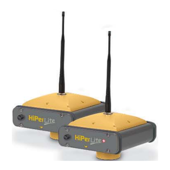
• The HiPer® Lite and HiPer® Lite+ receivers (Figure 1-1) • GPS and your receiver • Common receiver functions • Standard package contents and configurations • Receiver components • The Option Authorization File (OAF) Figure 1-1. HiPer Lite and HiPer Lite+ Receivers P/N 7010-0557 www.topconpositioning.com... -
Page 18: Overview
The HiPer Lite and HiPer Lite+ can receive and process both L1 and L2 signals, improving the accuracy of your survey points and positions. The dual-frequency and GPS+ features of HiPer Lite and HiPer Lite+ combine to provide the only real time kinematic (RTK) system accurate for short and long baselines. - Page 19 Principles of Operation user equipped with a GPS tracking receiver, who is on or near the Earth’s surface. The Global Navigation Satellite System (GLONASS), is the Russian Federation Ministry of Defense counterpart to GPS. At any one time, with a standard 15 degree angle, up to 10 or 12 GPS satellites are visible from any point on earth.
-
Page 20: Calculating Positions
30 seconds. • GPS satellites broadcast almanac data cyclically with a period of 12.5 minutes; GLONASS satellites broadcast almanac data cyclically with a period of 2.5 minutes. Topcon HiPer Lite and HiPer Lite+ Operator’s Manual... -
Page 21: Gps Positioning
Principles of Operation GPS Positioning Achieving quality position results requires the following three elements: • Accuracy – The accuracy of a position depends upon the number, signal integrity, and placement (also known as Dilution of Precision, or DOP) of satellites. –Differential GPS (DGPS) strongly mitigates atmospheric and orbital errors, and counteracts anti- spoofing signals the US Department of Defense... -
Page 22: Conclusion
Introduction Conclusion Surveyors can use Topcon GPS+ receivers to collect data from a network of satellites and control stations to triangulate precise points anywhere on Earth. This overview simply outlines the basics of GPS and GLONASS positioning. For more detailed information, visit the TPS website (www.topconps.com/gpstutorial/). -
Page 23: Standard Package Contents
• Static or dynamic modes Standard Package Contents The HiPer Lite or HiPer Lite+ comes in a real-time kinematic (RTK) package with two receivers, one as a Base Station and the other as a Rover Station (also, refer to the re-packaging instruction card). -
Page 24: Cables
14-008054-01 for E.U.) – used to connect the power charger to a power outlet • USB cable (for HiPer Lite+ only) (p/n 14-008031-01) – used to connect the receiver and an external device (hand- held controller or computer) via the USB ports Figure 1-2. -
Page 25: Power Supply/Charger
Standard receiver software includes: • PC-CDU – controller software that can run on a Windows-based computer. • FLoader – Topcon’s firmware loader; available on the Topcon website. • BTCONF – Topcon’s Bluetooth® wireless technology module configuration program; available on the Topcon website. -
Page 26: Literature
Manuals and other product information are also available on the Topcon website—www.topcongps.com/support/manuals.html or www.topcongps.com/hardware/index.html (then click on the appropriate product). The following manuals will also be useful for operating and caring for your receiver. These are also available on the Topcon website (www.topcongps.com/support/manuals.html). 1-10 • PC-CDU User’s Manual Topcon... -
Page 27: Getting Acquainted
• MINTER User’s Manual • BTCONF User’s Manual Getting Acquainted The HiPer Lite/HiPer Lite+ receiver is 159mm wide, 172mm deep, 88mm high, and weighs approximately 1.74kg. The receiver’s advanced design allows users to significantly reduce the number of cables required for receiver operation, with the ability to perform jobs more reliably and efficiently, especially when moving. -
Page 28: Internal Components
L1/L2 signals and GLONASS L1/L2 signals. Bluetooth Module A combination of software and hardware technology that makes the HiPer Lite and HiPer Lite+ mobile, wireless, GPS+ receivers that support a point-to-point serial profile. As such, the HiPer Lite/HiPer Lite+ can transfer and... -
Page 29: Power Board
GPS+ Receiver Board The receiver is supplied with one of the following receiver boards: • Euro-80 card for HiPer Lite receivers • Euro-112 card for HiPer Lite+ receivers Depending on the purchased options, these cards are capable of processing the following signals: •... -
Page 30: Battery
Introduction Table 1-2. Euro Card Options for HiPer Lite and HiPer Lite+ Euro Card Model Available Options Euro-80 GD (HE_GD) G: GPS L1 GD: GPS L1/L2 Euro-112 (HE_GGD) G: GPS L1 GD: GPS L1/L2 GG: GPS/GLONASS L1 GGD: GPS/GLONASS L1/L2 A WAAS-enabled TPS receiver allows simultaneous tracking of two WAAS satellites. -
Page 31: External Components
14 hours 10 hours Transmitting mode The Li-Ion batteries used in the HiPer Lite should run at no less than 98% capacity after 500 charging cycles. These batteries do not need to be drained before recharging. A battery charger (AC adapter) is included with the standard package. -
Page 32: Radome
Introduction Radome Figure 1-4 shows the radome components, which are the same for both HiPer Lite and HiPer Lite+ receivers. Figure 1-4. Radome (HiPer Lite+) • Internal antenna – Location of GPS/GLONASS internal antenna. • Modem antenna connector – Modem antenna connector used for internal modem RF connection. -
Page 33: Front Panel
Getting Acquainted Front Panel Figure 1-5 and Figure 1-6 on page 1-18 show front panel components for the HiPer Lite and HiPer Lite+ receivers. MINTER Reset Power Slant Height Measure Mark Figure 1-5. HiPer Lite Front Panel • MINTER – The Minimum INTERface for the receiver. - Page 34 –Port C used internally to connect the modem and receiver boards. –Port D used for communication between the receiver and an external device. • USB – Only available on the HiPer Lite+ receiver; used for high-speed data transfer and communication between the receiver and an external device. MINTER...
-
Page 35: Back Panel
Getting Acquainted Back Panel Figure 1-7 shows the back panel components for the HiPer Lite and HiPer Lite+; components are the same for both receivers. Vent Plug Slant Height Measure Mark Figure 1-7. HiPer Lite and HiPer Lite+ Back Panels •... -
Page 36: Option Authorization File (Oaf)
(www.topcongps.com/tech/index) or consult your TPS dealer. • Type of signal (standard L1; optional L2) • Memory (standard 0MB; for HiPer Lite, optional 1MB up to 512MB; for HiPer Lite+, optional 1MB up to 1GB) • Update rate standard 1Hz (optional 5, 10, or 20Hz) •... -
Page 37: Configuration
• Radio configuration • Bluetooth module configuration • Collecting almanacs Before you can begin using the HiPer Lite or HiPer Lite+ receiver, do the following: 1. Charge the batteries. See “Powering the Receiver” on page 2-2. 2. Configure the various parts of your receiver. See: •... -
Page 38: Powering The Receiver
2. Press the Reset key on the receiver. This will ensure that the receiver is in Normal mode for charging. The receiver will not charge in Zero Power Mode (see “Zero Power Mode” on page 4-21 for more information). Topcon HiPer Lite and HiPer Lite+ Operator’s Manual... -
Page 39: External Batteries
Powering the Receiver 3. Leave overnight. A nine-hour charge cycle will charge the batteries about 90%. A ten-hour charge cycle will fully charge the receiver. The internal batteries can not be overcharged. The speed of the charge depends on the Power and Charger settings on the Receiver Configuration screen, and whether the receiver is turned off or on. -
Page 40: Battery Charger
The power input for your battery charger should be AC between 90 and 264 V 1A (110 V AC) and between 47 Hz and 63 Hz. The battery charger outputs DC 12 V 2.5 A (30 W). Topcon HiPer Lite and HiPer Lite+ Operator’s Manual... -
Page 41: Turning On/Off The Receiver
REC LEDs are off). This delay (about 1 second) will prevent the receiver from being turned off by mistake. Power Management You can use Topcon’s PC-CDU software to manage your receiver’s power. The complete description of PC-CDU exceeds the scope of this manual, but can be found in the PC-CDU User’s Manual. - Page 42 • Off – receiver will not charge batteries • Charge A – receiver charges only battery A • Charge B – receiver charges only battery B • Auto – receiver automatically detects and charges both batteries Topcon HiPer Lite and HiPer Lite+ Operator’s Manual...
- Page 43 Powering the Receiver Figure 2-4. Select Charger Mode 5. Select the Power output modes Ports drop-down list to set power output on the serial ports (Figure 2-5). • On – the power board will deliver voltage on pin one of all serial port connectors when the receiver is turned on.
- Page 44 • Battery A – displays the voltage of battery A • Battery B – displays the voltage of battery B • Charger – displays the charger’s output voltage during battery charging Topcon HiPer Lite and HiPer Lite+ Operator’s Manual...
- Page 45 Powering the Receiver Figure 2-7. View Voltages Information 8. Select and check each of the Turn on/off Slots check boxes to enable the corresponding internal slots (Figure 2-8). 9. Select and check the Enable Low Power Mode check box to put the receiver’s processor into low power consumption mode (Figure 2-8).
-
Page 46: Charging Internal Batteries
If you remove a power supply cable before setting Power Mode to Auto, the receiver will be turned off. To turn it on, you will need to connect an external power supply once again. 2-10 Topcon HiPer Lite and HiPer Lite+ Operator’s Manual... -
Page 47: Checking Internal Battery Status
PC-CDU: • use a Bluetooth-enabled external device (computer) • use an RS232 cable • for the HiPer Lite+ only, use a USB cable and a computer with the TPS USB driver installed (available at http://www.topcongps.com/software/updates.html) -
Page 48: Establishing A Wireless Connection
Configuration Establishing a Wireless Connection The HiPer Lite and HiPer Lite+ receivers contain Bluetooth wireless technology that allows file transfer and synchronization between the receiver and any other external device that supports Bluetooth wireless technology; for example, an IPAQ, or a computer with USB-to-Bluetooth adapter or PCMCA-to-Bluetooth adapter installed. -
Page 49: Establishing An Rs232 Cable Connection
Establishing a USB Connection Make sure the computer has the TPS USB driver installed. 1. Using the USB cable and the HiPer Lite+, connect the USB port of your computer to the receiver’s USB port. 2. Press the power buttons on the receiver and computer to turn them on. -
Page 50: Establishing A Pc-Cdu Connection
(Figure 2-9). Figure 2-9. PC-CDU Main Screen Notice that the lower-left hand corner shows the receiver status as “Disconnected”. 2. Click File Connect (Figure 2-10). Figure 2-10. Connect to Receiver 2-14 Topcon HiPer Lite and HiPer Lite+ Operator’s Manual... - Page 51 Connecting the Receiver and a Computer 3. On the Connection Parameters dialog box, select the following parameters and click Connect: • for Bluetooth or RS232 connections (Figure 2-11): –Set the Connection mode (Direct). –Set the port for your computer (typically COM1, COM2 for RS232 connection and COM3, COM4, etc.
- Page 52 (if applicable), and flow control (if applicable) —display in the lower-left corner of the main window of PC-CDU. A timer begins to count up in the lower-right corner as well (Figure 2-13). Figure 2-13. PC-CDU Connection Established 2-16 Topcon HiPer Lite and HiPer Lite+ Operator’s Manual...
-
Page 53: Receiver Configuration
Receiver Configuration Receiver Configuration You use PC-CDU to configure the various parts of the receiver. Any settings you make using PC-CDU will be saved in the receiver’s memory, and will be reflected when you use the MINTER. The full range of PC-CDU configuration and function is outside the scope of this manual. - Page 54 • Enter the File name prefix. Use the last three digits of the receiver serial number.The receiver’s serial number and part number can be found on the bottom panel of the receiver. 2-18 Figure 2-16. Receiver Configuration – MINTER Tab Topcon HiPer Lite and HiPer Lite+ Operator’s Manual...
- Page 55 Receiver Configuration If your jobsite is in an area that has obstructions (buildings, trees, etc.), and/or the antenna location is near reflective objects, configure the receiver to reduce errors from these sources. WARNING WARNING Do not make other changes without consulting the PC-CDU User’s Manual.
- Page 56 6. Click the Loop Management tab, enable the following boxes, and click Apply (Figure 2-19). • Enable Co-Op tracking • Static Mode Figure 2-19. Advanced Configuration – Loop Management 7. Click OK to close the Receiver Configuration screen. 2-20 Topcon HiPer Lite and HiPer Lite+ Operator’s Manual...
- Page 57 Receiver Configuration 8. Click on File Disconnect, then File Exit to quit PC-CDU (Figure 2-20). Figure 2-20. Click Disconnect then Exit NOTICE NOTICE Disconnecting the receiver from the computer before exiting will eliminate any possible conflict in the management of your serial ports. Once the receiver is configured, the configuration will remain until you change it either using PC-CDU or clearing the NVRAM.
-
Page 58: Minter Configuration
The Minimum INTERface (MINTER) consists of three keys (Power, FN, and Reset) and four LEDs (STAT, REC, BATT, and RX) that control and display the receiver’s operation (Figure 2-21). The MINTER is the same for both the HiPer Lite and the HiPer Lite+ receiver. Reset... - Page 59 MINTER Configuration • Show the status of post-processing mode (static or dynamic) when performing a Post-Processing Kinematic survey with the help of FN key (REC LED). • Show the status (high charge, intermediate charge, or low charge) of the battery (BATT LED). •...
- Page 60 • Automatic File Rotation Mode (AFRM) on page 2-26 • FN key mode on page 2-27 • Initial data collection dynamic mode on page 2-28 • Data recording auto-start on page 2-28 2-24 Figure 2-24. Receiver Configuration – MINTER Tab Topcon HiPer Lite and HiPer Lite+ Operator’s Manual...
-
Page 61: Recording Interval
MINTER Configuration Recording Interval parameter This parameter specifies the message output interval into the log file when the MINTER FN key (pressed for 1–5 seconds) activates data logging. This setting is used for both logging a single log file, and logging receiver data in AFRM mode. Values are 1–86400 seconds. -
Page 62: Files Creation Mode
Values are 0 to 86400 seconds. The default value is zero seconds. • Files (total) – a counter that specifies how many multiple log 2-26 files must be created in AFRM until this mode automatically Topcon HiPer Lite and HiPer Lite+ Operator’s Manual... -
Page 63: Fn Key Mode
MINTER Configuration turns off. This counter decrements on every file rotation until it value becomes zero, then file rotation automatically stops. The counter initializes with AFRM. Note that a log file opens immediately after turning AFRM on. This startup file is not considered a file rotation event; the AFRM counter will not decrement. -
Page 64: Initial Data Collection Dynamic Mode
Table 2-2 on page 2-29 gives the different scenarios available and the results after power is restored to the receiver. “Specified file” refers to the file name entered in the Always append to file parameter. 2-28 Topcon HiPer Lite and HiPer Lite+ Operator’s Manual... - Page 65 MINTER Configuration Table 2-2. Data Recording Parameter Behavior Enabled Radio Button Results Before Power Failure Always Data logging will Receiver will Receiver will Receiver data not resume when resume data resume data logged to file power is restored. logging to the logging to the same specified.
-
Page 66: Radio Configuration
2. Follow the on-screen instructions to complete the installation. To uninstall Modem-TPS, use the Start menu on your computer: Click Start Programs Modem-TPS Uninstall Modem-TPS, and click Yes at the prompt. Then click OK when the uninstall completes. 2-30 Topcon HiPer Lite and HiPer Lite+ Operator’s Manual... - Page 67 Radio Configuration Once you have Modem-TPS installed, follow these steps to configure the radio modem. Modem-TPS automatically connects the receiver and modem boards for configuration purposes. When configuring radios, first configure the Base radio, then the Rover radio. 1. Using the RS232 cable, connect the serial port of your computer (usually COM1) to the receiver’s serial port A.
- Page 68 (bps) rate (bps) 0–9600 9600 9600 (recommended) 9600 19200 12000 19200 38400 57600 9600–12000 19200 12000 (recommended) 19200 38400 24000 38400 57600 12000–17000 19200 17000 (recommended) 19200 38400 24000 38400 2-32 57600 Topcon HiPer Lite and HiPer Lite+ Operator’s Manual...
- Page 69 Radio Configuration Table 2-3. Link Rate vs. Baud Rate Comparison (Continued) Use the following setting for... If data packet size (in bits) Transmitter Receiver is between... serial baud Link rate (bps) serial baud rate (bps) rate (bps) 17000–24000 38400 24000 38400 57600 57600...
- Page 70 –networks in the same location are assigned to different channel numbers. Otherwise, networks in close proximity will interfere with each other, and radio communication may fail. Figure 2-27. Modem-TPS Radio Link Tab 2-34 Topcon HiPer Lite and HiPer Lite+ Operator’s Manual...
- Page 71 Radio Configuration 5. Click the Serial Interface tab, set the following parameters, and click Apply (Figure 2-28): • Baud Rate – select a baud rate for the modem’s serial port. The same rate must be used for both the receiver and the modem.
- Page 72 (Figure 2-29). Figure 2-29. Modem-TPS Identification Tab 7. Click Help About to view Modem-TPS version and copyright information on the About Modem-TPS dialog box (Figure 2-30). Figure 2-30. About Modem-TPS 2-36 Topcon HiPer Lite and HiPer Lite+ Operator’s Manual...
-
Page 73: Bluetooth Module Configuration
Bluetooth Module Configuration 8. Click File Disconnect (Figure 2-31), then click File Exit to quit the program. Continue with other configuration or operation functions as needed. Figure 2-31. Click Disconnect then Exit Bluetooth Module Configuration Use BTCONF, the Bluetooth module’s configuration program, and your computer to: •... - Page 74 Figure 2-32. Bluetooth Module Configuration Main Screen Notice that the lower left corner shows a “Disconnected” status for the computer and Bluetooth module. For BTCONF version and copyright information, click the About button. 2-38 Topcon HiPer Lite and HiPer Lite+ Operator’s Manual...
- Page 75 Bluetooth Module Configuration 4. From the drop-down list in the upper left corner, select the computer serial port (usually COM1) used for communication (Figure 2-33). Figure 2-33. Select Communication Port and Click Connect 5. Click Connect to connect the computer and Bluetooth module (Figure 2-33).
- Page 76 Bluetooth module. 7. Enter up to 14 characters to set a unique name for the Bluetooth module (Figure 2-35), and click Apply. Figure 2-35. BTCONF Parameters Tab 2-40 Topcon HiPer Lite and HiPer Lite+ Operator’s Manual...
- Page 77 Bluetooth Module Configuration 8. To set security parameters (Figure 2-36), enter and enable the following, then click Apply: • Bluetooth PIN – enter up to 16 characters to specify a personal identification number for the Bluetooth module. • Encryption – enable to have the Bluetooth module encrypt wirelessly sent data.
- Page 78 Bluetooth module replies and corresponding commands on the computer terminal. If needed, click Apply. Figure 2-37. BTCONF Serial Interface Tab 10. Click Disconnect then Exit (Figure 2-38) to quit BTCONF. Figure 2-38. Click Disconnect then Exit 2-42 Topcon HiPer Lite and HiPer Lite+ Operator’s Manual...
-
Page 79: Collecting Almanacs
Collecting Almanacs Collecting Almanacs Each satellite broadcasts a message (almanac) which gives the approximate orbit for itself and all other satellites. If the receiver has an almanac, you can considerably reduce the time needed to search for and lock on to satellite signals. The receiver regularly updates the almanac and stores the most recent almanac in its Non-Volatile Random Access Memory (NVRAM). - Page 80 Configuration Notes: 2-44 Topcon HiPer Lite and HiPer Lite+ Operator’s Manual...
-
Page 81: Setup And Survey
• RTK Base station setup • RTK Rover setup • Basic surveying with the HiPer Lite or HiPer Lite+ receiver The HiPer Lite and HiPer Lite+ packages use one receiver as the Base station and the other as the Rover station. Receiver Setup To set up the receivers, you must: 1. -
Page 82: Step 1: Set Up The Receiver
• Slant – measured from the marker to the lower edge of the antenna slant height measure mark (SHMM) located on both end panels of the receiver. Topcon HiPer Lite and HiPer Lite+ Operator’s Manual... - Page 83 SHMM location.) SHMM 30.50mm 77.75mm Figure 3-1. HiPer Lite and HiPer Lite+ Antenna Offsets • SHMM to ARP vertical offset = 30.50mm • SHMM to ARP horizontal offset = 77.75mm Table 3-1gives the offset values for the receivers. Table 3-1. Antenna Offset Values for Receiver Options...
-
Page 84: Step 3: Collect Data
2. Release the FN key when the REC (recording) LED light turns green. This indicates that a file has opened and data collection has started. The REC LED blinks each time data is saved to the internal memory. Topcon HiPer Lite and HiPer Lite+ Operator’s Manual... -
Page 85: Surveying With The Receiver
Surveying with the Receiver Use PC-CDU to configure data logging. See “MINTER Configuration” on page 2-22 or refer to the PC-CDU User’s Manual. 3. When finished, press and hold the FN key until the REC LED light goes out. 4. To turn off the receiver, press and hold the power key until all lights go out, then release. - Page 86 Apply (Figure 3-2 on page 3-7): • Recording interval – 15 seconds • Elevation mask angle – 15 degrees • File name prefix – last 3 digits of receiver serial number Topcon HiPer Lite and HiPer Lite+ Operator’s Manual...
- Page 87 Surveying with the Receiver • LED blink mode switch – enable to start and stop static data recording using the FN key Figure 3-2. Configuration->Receiver->MINTER 3. Click the Advanced tab and then the Multipath tab, set the following parameters, then click Apply (Figure 3-3): •...
-
Page 88: Kinematic (Stop And Go) Survey
At this point, and each subsequent point, the receiver is changed to static mode to collect data. So, while moving, the Rover is in kinematic mode, and while collecting data, the Rover is in static mode. Topcon HiPer Lite and HiPer Lite+ Operator’s Manual... - Page 89 Surveying with the Receiver 1. Using PC-CDU, configure and set up the Base as described in “Static Survey” on page 3-5. 2. Using PC-CDU, click Configuration Receiver MINTER, and configure the Rover with the following parameters, then click Apply (Figure 3-5): •...
-
Page 90: Real-Time Kinematic Survey
1. Set up the Base station receiver’s antenna as described in “Receiver Setup” on page 3-1. 2. Press the power key on the receiver. 3-10 3. Check the STAT light for tracked satellites. Topcon HiPer Lite and HiPer Lite+ Operator’s Manual... - Page 91 Surveying with the Receiver 4. Connect your receiver and computer. See “Connecting the Receiver and a Computer” on page 2-11 for this procedure. 5. Click Configuration Receiver. 6. Click Set all parameters to defaults located at the bottom of the dialog box (Figure 3-6). Figure 3-6.
- Page 92 (span) completes. Examine the Base coordinates on the Base tab, they should correspond to the coordinates obtained from the average. Click Refresh if the coordinates are zeros. –Click Get from receiver. 3-12 Topcon HiPer Lite and HiPer Lite+ Operator’s Manual...
- Page 93 Surveying with the Receiver NOTICE NOTICE The reference geodetic coordinates specified on this tab relate to the antenna L1 phase center. Figure 3-8. Base Tab Configuration 10. Click the Ports tab and set the following port parameters (Figure 3-9 on page 3-14). Use serial port C for an internal Spread Spectrum 915 MHz modem.
-
Page 94: Setting Up An Rtk Rover
Use the following steps to set up an RTK Rover station. You should already have programmed the modem. Figure 3-10 on page 3-15 shows the hardware setup for a Rover station with an external controller. 3-14 Topcon HiPer Lite and HiPer Lite+ Operator’s Manual... - Page 95 Surveying with the Receiver Figure 3-10. Rover Station Setup 1. Set up the Rover station receiver’s antenna as described in “Receiver Setup” on page 3-1. 2. Connect the receiver and computer. See “Connecting the Receiver and a Computer” on page 2-11. 3.
- Page 96 RTK position (for the epoch to which the newly received RTCM/CMR message corresponds) or the current stand-alone position (while waiting for new RTCM/CMR messages coming from the base). • Select the antenna status during RTK, either Static or 3-16 Kinematic. Topcon HiPer Lite and HiPer Lite+ Operator’s Manual...
- Page 97 Surveying with the Receiver • Specify the Ambiguity fixing level (not applicable to RTK Float). The Ambiguity Fixing Level radio buttons govern the process of the RTK engine, fixing integer ambiguities. The RTK engine uses the ambiguity fix indicator when making decisions whether or not to fix ambiguities.
- Page 98 10–30 seconds. However, spread spectrum radios may take as long as 60 seconds to synchronize. Figure 3-13. PC-CDU Main Screen 3-18 Topcon HiPer Lite and HiPer Lite+ Operator’s Manual...
- Page 99 Surveying with the Receiver The geodetic coordinates displayed on the Geo tab are always computed in WGS84 and have four solution types. • Standalone – where receiver computes 3D coordinates in autonomous mode without using differential corrections. • Code differential – where the Rover receiver computes the current relative coordinate in differential mode using only pseudo ranges.
- Page 100 Setup and Survey Notes: 3-20 Topcon HiPer Lite and HiPer Lite+ Operator’s Manual...
- Page 101 • Checking and loading OAFs • Managing receiver memory • Clearing the NVRAM • Changing receiver modes • Checking and loading firmware Topcon receivers are built to operate independent of the receiver type. Minor exceptions are noted. P/N 7010-0557 www.topconpositioning.com...
-
Page 102: Chapter 4 Operation
Operation Using the MINTER The MINTER (Figure 4-1) is Topcon’s Minimum INTERface used to display and control data input and output, and is the same for all HiPer family receivers. Power Button Reset BATT (battery LED) STAT (status LED) REC (recording LED) -
Page 103: Reset Key
Using the MINTER Reset Key Pressing and holding the reset key for about one second causes: • a hard reset of the receiver. • the receiver to leave Zero Power Mode and return to Normal Mode. NOTICE NOTICE Only use this procedure if the receiver does not respond to commands or does not charge the internal batteries (is in Zero Power Mode). - Page 104 CDU (control display unit) applications or for data recording. This operation may require from fractions of a second to several minutes, depending on the circumstances and the amount of internal memory. Topcon HiPer Lite and HiPer Lite+ Operator’s Manual...
- Page 105 Using the MINTER Table 4-1. FN Key Functions and REC LED Status FN Key REC LED Status When data recording is off, and the FN key is... No light No data recording. Orange blink Internal file system test in progress. Not pressed No free memory;...
- Page 106 Release to stop data recording. seconds Pressed for 5–8 Release to turn serial port A baud rate seconds to 9600 bps. Pressed for > 8 No light No function (data recording still on). seconds Topcon HiPer Lite and HiPer Lite+ Operator’s Manual...
-
Page 107: Battery Led
• Blinking once a second – the batteries are being charged. • Blinking once every five seconds – the HiPer Lite uses the internal batteries for power. • Not blinking – the receiver is in Zero Power Mode or the internal batteries are completely discharged and no external power is connected. -
Page 108: Information Modes
–Orange: at least one blink is orange. –Red: no orange blink and at least one red blink. –Green: all other cases. • Sufficient data for position computation. • GPS S/N ratios are good (Table 4-2 on page 4-9). Topcon HiPer Lite and HiPer Lite+ Operator’s Manual... - Page 109 Using the MINTER • GLONASS S/N ratios are good (Table 4-2). • Oscillator’s frequency offset is less than three ppm. • Oscillator's Allan Variance is better than 2.7e-10. • Continuous tracking time is more than 15 minutes. Table 4-2. Signal-to-Noise (S/N) “Good” Ratios CA/L1 P/L1 P/L2...
-
Page 110: Downloading Files To A Computer
2. On the Connection Parameters dialog box, enable RTS/CTS handshaking (Figure 4-2). Figure 4-2. Connection Parameters – RTS/CTS Handshaking 3. Click File File Manager (Figure 4-3). 4-10 Figure 4-3. Open File Manager Topcon HiPer Lite and HiPer Lite+ Operator’s Manual... - Page 111 Downloading Files to a Computer 4. Click the Download path tab on the File Manager dialog box (Figure 4-4). Figure 4-4. Find Files to Download 5. Do one of the following: • Navigate to and open the folder in which to download and store files.
- Page 112 • Blue indicator – file in queue for downloading. • Red indicator – file currently downloading. • Green indicator – file has successfully downloaded. 4-12 Figure 4-6. Download Files – Status Indicators Topcon HiPer Lite and HiPer Lite+ Operator’s Manual...
-
Page 113: Deleting Files
Deleting Files 9. Click Exit on the File Manager dialog box. 10. Continue with other operations. Or, click File Disconnect, then File Exit to quit PC-CDU (Figure 4-7). Figure 4-7. Click Disconnect then Exit Deleting Files Use the following steps to delete files from your receiver. 1. - Page 114 6. Click Yes at the delete files confirmation dialog box. PC-CDU deletes the selected files. 7. Click Exit on the File Manager screen. 8. Continue with other operations. Or Click File Disconnect, 4-14 then File Exit to quit PC-CDU. Topcon HiPer Lite and HiPer Lite+ Operator’s Manual...
-
Page 115: Checking Receiver Options
Checking Receiver Options Checking Receiver Options For a complete list of options and their details, visit the Topcon website. You can check the status of your receiver’s options, and load any new OAFs, using the RS232 cable, a computer, and PC-CDU. Refer to the PC-CDU User’s Manual for a more complete description of... - Page 116 • yes or no – the option is either enabled or disabled. Figure 4-12. Option Manager 3. When finished, click Exit on the Option Manager screen, then 4-16 click File Disconnect to prevent conflicts with serial port management. Topcon HiPer Lite and HiPer Lite+ Operator’s Manual...
-
Page 117: Loading Oafs
Loading OAFs Loading OAFs Topcon Positioning System dealers provide customers with OAF files. For any OAF related questions, E-mail TPS at options@topconps.com. Please have your receiver ID number available (see “Checking Firmware Version” on page 4-22). 1. To load a new OAF, follow steps one and two in “Checking Receiver Options”... -
Page 118: Managing Receiver Memory
Clearing the NVRAM in your receiver can be interpreted as a “soft boot” in your computer. After clearing the NVRAM, your receiver will require some time to collect new ephemerides and almanacs (around 15 minutes). 4-18 Topcon HiPer Lite and HiPer Lite+ Operator’s Manual... -
Page 119: Using Minter To Clear Nvram
Clearing the NVRAM Clearing the NVRAM of your receiver will not delete any files already recorded in your HiPer Lite’s memory. However, it will reset your receiver to factory default values. In addition, the NVRAM keeps information about the receiver file system. -
Page 120: Changing Receiver Modes
Operation Changing Receiver Modes The HiPer Lite receiver has four modes, two information modes and two power modes: • Normal Mode • Extended Information Mode • Sleep Mode • Zero Power Mode See “Information Modes” on page 4-8 for a description of Normal Mode and Extended Information Mode. -
Page 121: Zero Power Mode
Changing Receiver Modes Zero Power Mode When your receiver is off, even in Sleep Mode, the power board will continue to draw power from the batteries. This means that if you fully charge your receiver, turn it off and store it, the receiver will drain its battery power in less than two months. -
Page 122: Checking Firmware Version
Use PC-CDU to check the firmware version of the receiver. NOTICE NOTICE The receiver should be loaded with firmware version 2.3p2 or newer for HiPer Lite, 2.3p3 or newer for HiPer Lite+. CAUTION CAUTION Do not use firmware versions 2.3p1 or older for HiPer Lite, 2.3p2 or older for HiPer Lite+. -
Page 123: Loading New Firmware
Loading New Firmware The About PC-CDU dialog box lists important information about the different hardware accessories and software properties. This list includes the following, which you will need if you contact TPS or your dealer: • Receiver model • Receiver ID •... -
Page 124: Receiver And Power Board Firmware
• main.ldp – the Receiver board Flash file • powbrd.ldr – the Power board RAM file NOTICE NOTICE You must load all three files when loading new firmware. These files must come from the same firmware package. 4-24 Topcon HiPer Lite and HiPer Lite+ Operator’s Manual... - Page 125 Loading New Firmware 1. In FLoader, click the Device tab and set the Device Type as Receiver. Then click Get from Device for device information (Figure 4-18). Figure 4-18. Set Device Type 2. Click the Program tab and set the Capture Method to Soft Break Capture (recommended) (Figure 4-19).
- Page 126 Reselect the correct file. 5. Select the Device tab and set the Device Type as Receiver’s Power Board. Then click Get from Device for device information (Figure 4-20). Figure 4-20. Set Device Type 4-26 Topcon HiPer Lite and HiPer Lite+ Operator’s Manual...
- Page 127 Loading New Firmware 6. Select the Program tab and set the Capture Method to Soft Break Capture (recommended) (Figure 4-21). Figure 4-21. Program Tab Settings 7. Browse for and select the Power board’s RAM file (Figure 4-21). 8. Click Load and wait until 100% of the power board file loads into your receiver.
-
Page 128: Bluetooth Module Firmware
These files must come from the same firmware package. 1. In FLoader, select the Device tab and set the Device Type as Receiver. Then click Get from Device for device information (Figure 4-22). Figure 4-22. Get Device Type 4-28 Topcon HiPer Lite and HiPer Lite+ Operator’s Manual... - Page 129 Loading New Firmware 2. Select the Program tab and set the Capture Method to Soft Break Capture (recommended) (Figure 4-23). Figure 4-23. Program Tab Settings 3. Browse for and select the Bluetooth module’s RAM file and Flash file (Figure 4-23). 4.
- Page 130 Operation NOTICE NOTICE If you selected an incorrect RAM or Flash file, an error message displays at the bottom of the dialog box. Reselect the correct file. 5. Click File Exit. 4-30 Topcon HiPer Lite and HiPer Lite+ Operator’s Manual...
-
Page 131: Troubleshooting
Chapter 5 roubleshooting In general, as long as you follow the maintenance and safety instructions provided in this manual, you should have few problems with your receiver. This chapter will help you diagnose and solve some common problems you may encounter with your receiver. WARNING WARNING Do not attempt to repair equipment yourself. -
Page 132: Power Problems
The receiver may have If after charging your internal batteries a defective charger or overnight, and your receiver is not defective internal powering, contact TPS Customer Support batteries. for advice. Topcon HiPer Lite and HiPer Lite+ Operator’s Manual... -
Page 133: Receiver Problems
Receiver Problems Receiver Problems The following are some of the most commonly encountered receiver problems. Problem The receiver cannot establish a connection to a computer or external controller. Causes Solutions The cable is not • Check that the cable connector is properly plugged in. - Page 134 PC-CDU. See etc.). “Connecting the Receiver and a Computer” on page 2-11. 2. Click Configuration Advanced Multipath Reduction and enable the two boxes. • Move to an area free of obstructions, if applicable. Topcon HiPer Lite and HiPer Lite+ Operator’s Manual...
- Page 135 Receiver Problems Problem The receiver cannot obtain Code Differential and/or RTK solutions. Causes Solutions Incorrect Base Specify the correct coordinates for the coordinates entered. Base station using PC-CDU or other suitable field data collection software. The receiver is not • If the receiver should function as a configured as a Base or Base, ensure it has the proper Rover.
- Page 136 • See “Radio Configuration” on The link rate is the rate page 2-30for checking the current link at which data transmits rate and changing the link rate. over the RF link. Topcon HiPer Lite and HiPer Lite+ Operator’s Manual...
- Page 137 Receiver Problems The specified baud rate • Change the baud rate to that which is not compatible with your modem supports. See the the baud rates the modem’s manual for baud rate support modem supports. information. • See “Radio Configuration” on The baud rate is the page 2-30 for checking the current rate at which the...
-
Page 138: Bluetooth Problems
COM port specified in the differs from the one BTCONF communication port drop- selected in BTCONF. down list. See “Bluetooth Module Configuration” on page 2-37 for details. Topcon HiPer Lite and HiPer Lite+ Operator’s Manual... - Page 139 Bluetooth Problems The receiver port used 1. Connect your receiver and a for connection is not in computer using a free port (see Command mode. “Connecting the Receiver and a Computer” on page 2-11) and start PC-CDU. 2. Click Configuration Receiver Ports.
- Page 140 3. Re-connect to the Bluetooth module. The receiver does not Contact your dealer to purchase a have a Bluetooth Bluetooth enabled receiver. module. 5-10 Topcon HiPer Lite and HiPer Lite+ Operator’s Manual...
- Page 141 Bluetooth Problems Error Message Open COM# port failed: Access is denied. Causes Solution Another application • Close the application, then re-connect. uses the computer port • Connect the receiver via another, dedicated for unused computer port. connection Problem After searching for available devices, none are discovered. Causes Solution The receiver is not...
- Page 142 Bluetooth module, remove it from changed. the list of discovered Bluetooth devices using the Bluetooth manager program (supplied with the device used to manage the receiver). 2. Repeat the search. 5-12 Topcon HiPer Lite and HiPer Lite+ Operator’s Manual...
-
Page 143: Radio Modem Problems
Radio Modem Problems Radio Modem Problems The following are some of the most commonly encountered spread spectrum radio modem problems. Problem RX LED flashes red. Causes Solutions A fault condition has • Check that the radio modem’s antenna been detected. is undamaged. - Page 144 Unknown radio Contact your Dealer to equip the receiver modem type is with the correct spread spectrum radio installed. modem. 5-14 Topcon HiPer Lite and HiPer Lite+ Operator’s Manual...
-
Page 145: Obtaining Technical Support
Obtaining Technical Support Problem Modem-TPS displays the following error message: “Open COM# port failed: Access is denied.” Causes Solutions Another application • Close the application, then re-connect. uses the computer port • Connect the receiver via another, dedicated for unused computer port. connection Obtaining Technical Support If the troubleshooting hints and tips in this Operator’s Manual fail... -
Page 146: E-Mail
Website The Topcon Positioning Systems website provides current information about Topcon’s line of products. The support area of the website provides access to frequently asked questions, configuration procedures, manuals, e-mail support, etc. To access the TPS website home page, use: www.topconpositioning.com... -
Page 147: External Antenna Setup
Appendix A xternal Antenna Setup For machine control applications, the HiPer Lite+ receiver comes configured with an external antenna port (Figure A-1). External Antenna Vent Plug Connector Slant Height Measurement Mark Figure A-1. HiPer Lite+ with External Antenna Connector 1. Attach the antenna to a tripod or bi-pod and center it over the point at which data will be collected. - Page 148 Antenna Radius A, Vertical Offset C, Slant Offset MC-A1 89.7mm 54.3mm (L1) 26.8mm (L1) 60.5mm (L2) 33.0mm (L2) 3. Record the antenna height, point name, and start time in the field notes. Topcon HiPer Lite and HiPer Lite+ Operator’s Manual...
- Page 149 4. Attach the flexible RF cable from the external antenna to the antenna connector on the back panel of the receiver. 5. Continue with other setups or operations as needed. The receiver antenna default is set to Auto, allowing the receiver to detect automatically the available antenna (whether internal or external).
- Page 150 External Antenna Setup Notes: Topcon HiPer Lite and HiPer Lite+ Operator’s Manual...
-
Page 151: Appendix B
Appendix B pecifications This TPS product is a 20-channel GPS receiver with an internal spread spectrum radio, a Bluetooth wireless technology module, and a rugged aluminum housing complete with MINTER and cable connectors. Receiver Specifications Table B-1 lists receiver component details. Table B-1. -
Page 152: Specifications
Low signal tracking Advanced Multipath mitigation WAAS Adjustable PLL and DLL parameters Radio Link Frequency 902-928 MHz Signal structuring Frequency-hopping spread spectrum Hopping Pattern 5 per band, user-selectable Hopping channels Occupied bandwidth 100 KHz Topcon HiPer Lite and HiPer Lite+ Operator’s Manual... -
Page 153: Receiver Specifications
Receiver Specifications Table B-1. Receiver Specifications (Continued) Component Details Frequency modulation FSK, 64 Kbps technique System gain 140 dB Network topology Point-to-point, Point-to-multipoint Radio Transmitter Output power 250 mW (24 dBm)/1 W (30 dBm), user-selectable Radio Receiver Sensitivity -110 dBm at 10-4 BER Dynamic range 110 dB Radio Data Communications... - Page 154 10cm code phase and 0.1mm carrier phase precision RTCM SC104 version 2.1, 2.2, and 2.3 I/O Multiple Base RTCM Geoid and Magnetic Variation models RAIM Different DATUMs support Output of grid coordinates CMR and CMR+ support Topcon HiPer Lite and HiPer Lite+ Operator’s Manual...
- Page 155 Internal Memory Compact flash card (not removable) Capacity Standard – 0 MB Max – 512 MB (HiPer Lite) or 1 GB (HiPer Lite+) Logging Time 53 hours (8 MB, 15sec, L1/L2, 7 satellites) Logging Interval 0.05 to 86400 seconds, depending on purchased...
- Page 156 -30 C° to + 60 C° with batteries temperature Storage temperature -40 C° to +75 C° with batteries Physical Enclosure Aluminum extrusion, rainproof Color Topcon Yellow Dimensions W:159 x H:88 x D:172 mm Weight 1.74 kg Topcon HiPer Lite and HiPer Lite+ Operator’s Manual...
- Page 157 Receiver Specifications Table B-1. Receiver Specifications (Continued) Component Details Antenna Internal Battery Two internal Controller External Mounting 5/8-11 Seals Silicon (molding in Color) Keys Three keys: Power – On/Off Function (FN) – start/stop data logging; switch information mode. Reset – receiver hardware reset LEDs Four LEDs: STAT –...
- Page 158 The receiver can record raw data at another interval during RTK operation Status Fix, Float, DOP, Data Link Status, Modem Latency, Common satellites, Percentage of fixing Results RTK coordinates, HRMS, VRMS, Covariance Matrix Topcon HiPer Lite and HiPer Lite+ Operator’s Manual...
- Page 159 Receiver Specifications Table B-1. Receiver Specifications (Continued) Component Details Ambiguity fixing Selectable thresholds level Low: 95%; Medium: 99.5%; High: 99.9% Tracking Functions Multi-path reduction Code and Carrier PLL/DLL setting Bandwidth, order, adjustable Co-op tracking loop On/Off, Static Mode, Bandwidth of individual PLL, setting Bandwidth of common PLL Smoothing interval...
- Page 160 Specifications Cinderella days is an option that turns a single frequency, GPS receiver into a dual-frequency, GPS+GLONASS receiver for 24 hours every other Tuesday at GPS midnight. Refer to Topcon’s website for more information and specific Cinderella day dates. NOTICE...
-
Page 161: Connector Specifications
Connector Specifications Connector Specifications The following sections list HiPer Lite and HiPer Lite+ connector details. Radio (Modem) RF Connector The Spread Spectrum modem (TPS) connector type (Table B-2) is a reverse-TNC female RF connector. Table B-2. Spread Spectrum Modem Connector Specifications... -
Page 162: Serial C-Rs232 Connector
Table B-4 gives the RS232 cable connector specifications. Table B-4. RS232 Connector Specifications Number Signal Name Details Power_OUT Power Output (Supplied Voltage) Signal ground Clear to send Request to send B-12 Receive data Topcon HiPer Lite and HiPer Lite+ Operator’s Manual... -
Page 163: Usb Connector
Transmit data Not used USB Connector Only available on HiPer Lite+ receivers, the USB connector is a sealed receptacle, 5 pin TPS cable connector (Figure B-3). Figure B-3. USB Connector for GGD Options Table B-5 gives the USB connector specifications. - Page 164 Specifications Notes: B-14 Topcon HiPer Lite and HiPer Lite+ Operator’s Manual...
-
Page 165: Safety Warnings
Warnings General Warnings NOTICE NOTICE To comply with RF exposure requirements, maintain at least 20cm between the user and the HiPer Lite receiver. WARNING WARNING TPS receivers are designed for survey and survey related uses (i.e., surveying coordinates, distances, angles and depths, and recording such measurements). -
Page 166: Internal Battery Pack Warnings
– Do not attempt to open the battery pack or replace – Do not disassemble the battery pack. – Do not charge in conditions different than specified. – Do not use other than the specified battery charger. Topcon HiPer Lite and HiPer Lite+ Operator’s Manual... -
Page 167: Usage Warnings
Usage Warnings – Do not short circuit. – Do not crush or modify. Usage Warnings CAUTION CAUTION If this product has been dropped, altered, transported or shipped without proper packaging, or otherwise treated without care, erroneous measurements may occur. The owner should periodically test this product to ensure it provides accurate measurements. - Page 168 Safety Warnings Notes: Topcon HiPer Lite and HiPer Lite+ Operator’s Manual...
-
Page 169: Warranty Terms
1. The warranty against defects in Topcon battery, charger, or cable is 90 days. P/N 7010-0557... - Page 170 Warranty Terms Notes: Topcon HiPer Lite and HiPer Lite+ Operator’s Manual...
- Page 171 ndex green orange 2-26, 5-7 AFRM 2-43 Almanac 1-14 Battery 4-18 and NVRAM 1-9, 1-15, 2-4 charger broadcast data 2-11 status 2-43 collecting Baud rate ephemerides See Set baud rate 4-27, 5-4 update 1-12, 2-12 Bluetooth 2-25 Always append to file 2-38 configuration 1-6, 1-12...
- Page 172 FLoader Information mode 4-12 indicators See also Receiver modes 4-17 Dual frequency extended normal 4-20 sleep 4-8–4-9 STAT LED 2-25 4-21 Elevation mask zero power Index Initial data collection dynamic mode 2-28 Topcon HiPer Lite and HiPer Lite+ Operator’s Manual...
- Page 173 Index 1-17 Install MINTER 2-37 2-23 BTCONF configuration 4-23 2-22 FLoader functions 2-30 2-24, 2-25–2-28 Modem-TPS parameters 4-17 using 2-11 USB driver Modem 1-12, 1-16 1-16 Internal antenna antenna connector 3-2, 3-3 2-31–2-37 offset configuration 2-30 settings Modem configuration setup Modem LED Internal batteries See RX LED...
- Page 174 Receiver differences Pinnacle 4-20 Receiver modes 1-9, 2-30 radio configuration See also EIM 2-30 Spread Spectrum See also Normal Mode Start/stop data recording 4-8–4-9 extended Index 4-20 sleep mode 4-21 zero power Topcon HiPer Lite and HiPer Lite+ Operator’s Manual...
- Page 175 Index 4-2, 4-8 STAT LED 4-2, 4-8–4-9 blink pattern 4-21 Zero power mode reset key green orange 3-5–3-8 Static survey configuration MINTER parameters Stop and Go survey configuration Survey configuration static stop and go Surveying kinematic 3-10 3-5–3-8 static stop and go Switch information modes 1-6, 4-8, C-3 Test...
-
Page 176: Index
Index Notes: Index Topcon HiPer Lite and HiPer Lite+ Operator’s Manual... - Page 177 Notes Notes: Notes www.topconpositioning.com...
- Page 178 Notes Notes: Notes Topcon...
- Page 180 Topcon Positioning Systems, Inc. Phone: 925 • 460 • 1300 Fax: 925 • 460 • 1315 © 2004 Topcon Corporation. All rights reserved. No unauthorized duplication. HiPer Lite & HiPer Lite+ Operator’s Manual P/N: 7010-0557 Rev. C Printed in U.S.A. 4/04 500...
Need help?
Do you have a question about the HiPer Lite and is the answer not in the manual?
Questions and answers