Table of Contents
Advertisement
Quick Links
LogBox Wi-Fi
INSTRUCTION MANUAL V1.0x E
FCC
This device has been tested and complies with the parameters for a Class A digital device, pursuant to Part 15 of the FCC Rules. Such limits are
designed to provide reasonable protection against harmful interference when the device is operated in a commercial environment. This device
generates, uses, and can radiate radio frequency energy and, if not installed and used in accordance with the instructions in this manual, may
cause harmful interference to radio communications.
Any changes or modifications not expressly approved by the party responsible for compliance could void the user's authority to operate the device.
RF Exposure: It is necessary to keep 20 cm between the antenna and the user and the transmitter module cannot be co-located with any other
transmitter or antenna.
Canada
This Class A device complies with Canadian standard ICES-003.
Cet appareil numérique de la classe A est conforme à la norme NMB-003 du Canada.
CE Mark
This is a Class A device. In a domestic environment, it may cause radio interference and require the user to take proper measures.
ANATEL
This device is homologated by ANATEL, in accordance with the procedures regulated by Resolution 242/2000, and meets the technical
requirements applied.
This device is operated in a secondary fashion, that is, it is not entitled to protection against harmful interference, even from the same type of
stations, and it cannot cause interference to systems operating on a primary basis.
For more information, see the ANATEL website www.anatel.gov.br.
NOVUS AUTOMATION
1/53
Advertisement
Table of Contents

Related Manuals for Novus LogBox Wi-Fi


Summary of Contents for Novus LogBox Wi-Fi
- Page 1 LogBox Wi-Fi INSTRUCTION MANUAL V1.0x E This device has been tested and complies with the parameters for a Class A digital device, pursuant to Part 15 of the FCC Rules. Such limits are designed to provide reasonable protection against harmful interference when the device is operated in a commercial environment. This device generates, uses, and can radiate radio frequency energy and, if not installed and used in accordance with the instructions in this manual, may cause harmful interference to radio communications.
-
Page 2: Table Of Contents
WRITE HOLDING REGISTERS – 0X06 ..............................24 8.1.3 WRITE MULTIPLE HOLDING REGISTERS – 0X16 ..........................24 REGISTERS TABLE....................................24 DATA LOGGING .......................................30 ALARMS ........................................31 CONFIGURATION SOFTWARE ................................32 11.1 CONFIGURING LOGBOX WI-FI WITH NXPERIENCE ..........................32 11.1.1 GENERAL PARAMETERS ..................................32 11.1.2.1 INFORMATION......................................32 11.1.2.2 DISPLAY ........................................32 11.1.2.3 CLOCK ........................................ - Page 3 SUPPORT FOR CFR 21 PART 11 AND RDC 17:2010 VALIDATION......................48 TROUBLESHOOTING ....................................49 16.1 START/STOP MODES ....................................49 16.2 CLOCK ........................................49 16.3 ALARM INFORMATION ....................................49 16.4 ANALOG INPUTS......................................49 16.5 UNREGISTERED ALARMS ..................................49 16.6 COMMUNICATION LINK LOSS ................................49 TECHNICAL SPECIFICATIONS ................................50 17.1 SENSORS RANGE AND ACCURACY ..............................51 WARRANTY ......................................53 NOVUS AUTOMATION 3/53...
-
Page 4: Safety Alerts
Safety recommendations should be observed to ensure user safety and to prevent damage to the device or system. If the device is used in a manner other than that specified in this manual, the safety protections may not be effective. NOVUS AUTOMATION 4/53... -
Page 5: Introduction
LogBox Wi-Fi also has a buzzer for audible alerts and a digital output that can be used as an alarm output or as an electronic key to power sensors and can be controlled by several protocols, such Modbus-TCP and MQTT, for example. -
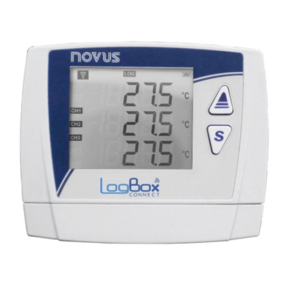
Page 6: Display And Navigation
See below an illustration of the display with a description of each symbol’s functionality. Fig. 01 – LogBox Wi-Fi Display Information : It remains lit while LogBox Wi-Fi has a valid IP on the wireless network to which you are connected. If the device is set to wake up by ●... -
Page 7: Operation Keys
OPERATION KEYS To navigate between the screens, LogBox Wi-Fi has 2 keys: . Each key, depending on the current navigation screen, has two or more features: ● Short touch (less than 2 seconds): ○ Proceeds to the next screen if the current screen mnemonic is being displayed. - Page 8 Line 2: Month.Day of the event. Line 3: Hour:Minute of the event. Displayed for two seconds before accessing This screen will be updated for each event the "Digital Input - Event Log or Record detected at the digital input. Control" screen. NOVUS AUTOMATION 8/53...
- Page 9 Key held down or long touch: No action. Both keys held down: No action. Displayed for two seconds before accessing This screen is static and always has the the "Information" screen. same value for the same device. NOVUS AUTOMATION 9/53...
- Page 10 Key held down or long touch: No action. Key held down or long touch: No action. Both keys held down: No action. Displayed for two seconds before accessing This screen will be updated whenever the IP the "IP Low" screen. is changed. NOVUS AUTOMATION 10/53...
- Page 11 Key held down or long touch: No action. Both keys held down: No action. Displayed for two seconds before accessing This screen will be updated according to the the "Wi-Fi LQI" screen. Wi-Fi signal strength. Table 01 – Navigation Keys NOVUS AUTOMATION 11/53...
-
Page 12: Operation Autonomy
4. OPERATION AUTONOMY LogBox Wi-Fi is powered by an external power supply, with a 10 to 30 VDC input, or USB port. The device can optionally be powered by four standard "AA" batteries (1.5 V each) which, in the event of a power failure in the power supply source, will keep it running for at least two years. In this case, to reduce consumption, the Wi-Fi interface will be disabled. -
Page 13: Input Signals Reading
5. INPUT SIGNALS READING LogBox Wi-Fi allows users to choose, in addition to the channels to be registered and sensor types, some configurations that provides flexibility to several applications, offering the possibility of weighing the energy resources (battery life) and data storage (length of log memory). Thus, it is possible to configure the device with the following parameters: ●... -
Page 14: Measurement And Indication Of Input Types
● Internal Diagnostic Sensors: ○ Inform the voltage of the possible LogBox Wi-Fi power supply sources; ○ The maximum resolution for the internal diagnostic sensors is 0.01 V; ○ You can configure them to be displayed with 0, 1, or 2 decimal places;... - Page 15 Table 02 – Measurement and indication of input types by LogBox Wi-Fi LogBox Wi-Fi allows you to configure settings to be applied to analog sensor readings. These settings can be used to correct errors in the sensor or process in which the sensor is installed and applied individually for each analog channel. Two adjustment modes are provided by the device: Offset: Allows each analog channel to choose an Offset value to be added to the channel reading indication.
-
Page 16: Digital Input
If the sensor is a Dry Contact sensor type, the LogBox Wi-Fi will be able to count to 10 pulses per second. For PNP and NPN sensors, 2000 pulses per second. However, it is important to note that these pulses will accumulate within the log range. Thus, it is necessary to evaluate the sensor maximum frequency so that it does not exceed 65535 counts (16 bits) within the log range and overflow the register that accumulates them. -
Page 17: Event Log
(user-customized unit). In the same example, it is possible to assume that the log range is 20 seconds. Thus, if the sensor gives 20 pulses per second, the LogBox Wi-Fi will register 400 pulses per range, displaying 40 parts per minute (((20 pulses/s)/(30 pulses/part)) * 60 (1 min) = 40) for the user. -
Page 18: Digital Output
4-20 mA transmitters, for example, can be fed by the digital output pin, so that they are only turned on when they are read – which would save energy from the LogBox Wi-Fi external power supply, which can be a 12 V battery. In the "Auxiliary Electronic Switch" mode, it will be necessary to configure how long before each acquisition the digital output must be triggered. -
Page 19: Mqtt Protocol
Example: {"config_receive":"ok","error_type":"none","parameter":"none"} 7.1.5 IDENTIFICATION TOPIC novus/neighbor: Topic for the publication of the identify from the device(s) connected to the Broker. It shall be published at the latest every • five minutes. Example: {"model":"LogBox Wi-Fi", "serial":12345678, "ip":"192.168.88.10", "mac":"B0:38:29:5D:FE:B1" ,"lqi":-40,"firmware_version":1.00} * The <sn>... -
Page 20: Inscription Topic
Topic section of this chapter. If there is any kind of error during the command request, the device will still send a response via the novus/<sn> /response topic, but it will inform the type of error found, as described in Table 6. -
Page 21: Frame Parameters
Informs the defined tag for each channel through NXperience software. See the Configuration Software chapter for more information on how to set the tag for each channel. tag_units Informs the unit tag defined for each channel using the NXperience software: Celsius (°C) or Fahrenheit NOVUS AUTOMATION 21/53... -
Page 22: Timestamp
Dynamic Array: Send information only about the enabled variables, grouping each parameter inside brackets. • o Status: {"n_channels":2,"timestamp":43277.40706019,"battery":5.69,"value_channels":[22.300,22.300],"alarm_low":[1,0],"alarm_high":[0,1],"buzzer _state":0} o Config: {"n_channels":2,"timestamp":43277.57538194,"frame_format":"array_dynamic","channels_enabled":[1,1],"hash":"9401ACBDFFD105D653 DAE5222470B47127455BBC","gmt":- 180,"tag_channels":["Analog1","Analog3"],"tag_units":["Celsius","Celsius"],"sp_alarm_low":[40.500,0.000],"sp_alarm_high":[0.000,20.000]} Static Descriptive: Send information about all variables, even those that are not enabled, grouping each variable in unit mode. • o Status: {"n_channels":4,"timestamp":43277.40924769,"battery":5.69,"ch_dig":0.000,"ch_analog_1":22.600,"ch_analog_2":0.000,"ch_analog_3":22. 600,"alarm_low_dig":0,"alarm_low_analog_1":1,"alarm_low_analog_2":0,"alarm_low_analog_3":0,"alarm_high_dig":0,"alarm_high_analog_ 1":0,"alarm_high_analog_2":0,"alarm_high_analog_3":1,"buzzer_state":0} NOVUS AUTOMATION 22/53... -
Page 23: Boolean Format
The NXperience Boolean Format parameter (see MQTT Protocol section of the Configuration Software chapter) tells you how Boolean variables will be displayed within the JSON frame, as you can see in the examples below. Numeric: • {"n_channels":4,"timestamp":43277.45657407,"battery":5.69,"value_channels":[0.000,23.400,0.000,23.400],"alarm_low":[0,1,0,0],"alarm_high":[ 0,0,0,1],"buzzer_state":0} String: • {"n_channels":4,"timestamp":43277.45446759,"battery":5.69,"value_channels":[0.000,23.300,0.000,23.300],"alarm_low":[false,true,false,false] ,"alarm_high":[false,false,false,true],"buzzer_state":false} NOVUS AUTOMATION 23/53... -
Page 24: Modbus-Tcp Protocol
COMMANDS It is important to note that the "Slave ID" parameter of the Modbus-TCP protocol can be filled with any value between 0 and 255. LogBox Wi-Fi is not a gateway, so it is only necessary to enter the IP address to perform the communication. - Page 25 Maximum alarm status on digital channel. Stores information if the channel ever reached the maximum alarm. 0. Never alarmed; 1. Already alarmed. CH1_STATUS Analog channel status 1. 1. Ok; 2. Underflow; 3. Overflow; 4. Cold joint error; 5. Open sensor. NOVUS AUTOMATION 25/53...
- Page 26 For linear sensors, the decimal point is configured. CH2_ALARM_MIN_STATUS Analog channel minimum alarm status 2. Decimal places: 1. For temperature sensors and the cold joint; 2. For battery voltage and external power supply. For linear sensors, the decimal point is configured. NOVUS AUTOMATION 26/53...
- Page 27 MQTT_LAST_UPDATE_YEAR Year of last submission to the MQTT Broker. MQTT_LAST_UPDATE_MONTH Month of last submission to the MQTT Broker. MQTT_LAST_UPDATE_DAY Day of last submission to the MQTT Broker. MQTT_LAST_UPDATE_HOUR Hour of last submission to the MQTT Broker. NOVUS AUTOMATION 27/53...
- Page 28 1176 CH2_ALARM_MIN Analog channel 2 minimum alarm setting. Decimal places: 1. For temperature sensors and the cold joint; 2. For battery voltage and external power supply. For linear sensors, the decimal point is configured. NOVUS AUTOMATION 28/53...
- Page 29 Analog channel 3 maximum alarm setting. Decimal places: 1. For temperature sensors and the cold joint; 2. For battery voltage and external power supply. For linear sensors, the decimal point is configured. Table 10 – Registers table that allow writing NOVUS AUTOMATION 29/53...
-
Page 30: Data Logging
9. DATA LOGGING Data logging will be done in the LogBox Wi-Fi internal memory. The internal memory capacity is up to 140,000 logs. The number of logs that can be stored in the internal memory depends basically on the number of input channels that are enabled, as well as factors such as recording or not recording the digital input event. -
Page 31: Alarms
10. ALARMS LogBox Wi-Fi has four channels. It is possible to set a minimum alarm and a maximum alarm for each channel. Alarms will be displayed and can be configured to trigger an internal Buzzer for audible warning and a Digital Output for user control. -
Page 32: Configuration Software
Date/Time: Allows you to set the date/time used to set the device clock. • GMT: Allows you to configure the GMT of the place where the device will be used (preferably during first use). By default, LogBox Wi-Fi is set •... -
Page 33: Analog Channels Parameters
Read Channel: Allows you to obtain the device’s values during a custom calibration. • Add: Allows you to enter the "Measured" and "Desired" pair in the Custom Calibration table. • Modify: Allows you to modify the "Measured" and "Desired" pair in the Custom Calibration table. • NOVUS AUTOMATION 33/53... -
Page 34: Digital Channel Parameters
The minimum configurable debounce time is 50 milliseconds; the maximum are 6 seconds. User Unit: Allows you to configure the flow unit related to the pulses counted in the Digital Input. LogBox Wi-Fi provides nine flow units. If one •... -
Page 35: Event Log Or Logs Control Mode
Alarm Status: In this mode, the digital output will follow the current and general alarm status. If any channel is in an alarm situation, the Digital Output will be enabled. If no channel is set to alarm, the Digital Output will be disabled. NOVUS AUTOMATION 35/53... -
Page 36: Data Logging Configuration
Never or Date/Time or Keyboard or Software or Digital Input Date/Time Never or Date/Time or Keyboard or Software or Digital Input Digital Input Never or Digital Input Keyboard Never or Keyboard Software Never or Software Daily Daily Table 12 – Logs End Modes NOVUS AUTOMATION 36/53... -
Page 37: Communication Parameters
LogBox Wi-Fi does not have an external power supply and is running on batteries, this interface will be automatically disabled. Access Point SSID: Allows you to enter the name of the Wi-Fi network to which LogBox Wi-Fi will try to connect to. The field accepts up to 32 •... -
Page 38: Modbus-Tcp Protocol
11.2 DIAGNOSTICS On the LogBox Wi-Fi configuration screen in NXperience, there is the "Diagnostics" screen. By clicking on it, the software will monitor some device states. The information update range is 1 second. See below for more details on monitored information: 11.2.1 DATA LOGGING... -
Page 39: Channels
LogBox Wi-Fi memory. Log Control: Allows you to start or pause LogBox Wi-Fi data logging. In order for this option to be active, the "By Software" parameter must •... - Page 40 State: Displays information about the device’s current state. o IP Address: Displays information about the device’s IP address. o MAC Address: Displays information about the device’s MAC address. o Quality Connection: Displays information about the connection quality. NOVUS AUTOMATION 40/53...
-
Page 41: Installation
To assist in the installation aesthetics, two openings in the lower part of the fixing bracket can be used to pass the sensors that are connected to the device. In addition to that, this bracket has a ring that allows the placement of a padlock preventing LogBox Wi-Fi from being removed from the installation location. -
Page 42: Dimensions
Fig. 20 – Fitting the protection cover 12.1.1 DIMENSIONS Fig. 21 – LogBox Wi-Fi dimensions To open the battery compartment, press the cover in the arrows region and push it in from the inside out. Fig. 22 – Batteries cover... -
Page 43: Electrical Installation
12.2.3 ELECTRICAL CONNECTIONS LogBox Wi-Fi has 4 detachable connection terminal blocks for connection of external power supply, digital output load, digital input sensor, and analog sensors for each of the 3 available analog channels. Fig. 23 illustrates electrical connections in a basic way: Fig. -
Page 44: Digital Output
The connection to the Digital Input with a PNP-type sensor is made at the terminals according to the following image. NPN Connection Sensor The connection to the Digital Input with a NNP-type sensor is made at the terminals according to the following image. NOVUS AUTOMATION 44/53... -
Page 45: Analog Inputs
The connection to the channels is made at the terminals according to the following image. The three-wire connection from the Pt100 sensor element to the LogBox Wi-Fi input guarantees the error cancellation caused by the wires resistance. The three wires should have the same gauge and length. -
Page 46: Communication Interfaces
13.2 WI-FI LogBox Wi-Fi has an 802.11 interface in 2.4 Ghz b/g/n standards for sending registered data through protocols compatibles with the device. The Wi-Fi interface also sends some device’s configuration parameters of the LogBox Wi-Fi through these same protocols and performs the firmware update through Over the Air technology. -
Page 47: Over The Air (Ota) Firmware Update
14. OVER THE AIR (OTA) FIRMWARE UPDATE The LogBox Wi-Fi Wi-Fi module can be upgraded using Over the Air (OTA) technology. To perform this procedure, you must know the device’s IP. After that, you will need to access it through a Browser. In the address bar, you must enter the device’s IP address (192.168.12.33, for example). -
Page 48: Cfr 21 Regulation
15.1 SUPPORT FOR CFR 21 PART 11 AND RDC 17:2010 VALIDATION LogBox Wi-Fi can be part of a validated system by offering the following features for compliance support: • Device development follows the company’s quality standard. It has the ISO 9001 certification and follows good manufacturing practices, the basis for compliance with GAMP 5 requirements in validation model V. -
Page 49: Troubleshooting
• Immediate Start: "Date/Time" or "Daily" parameters will return when the device is powered up again and is able to resume the clock. 16.2 CLOCK In the case of a power outage, LogBox Wi-Fi cannot reset the clock on its own. Thus, if the clock information is lost, the device will not log until the clock is reset. -
Page 50: Technical Specifications
17. TECHNICAL SPECIFICATIONS CHARACTERISTICS LOGBOX WI-FI 3 analog inputs Input Channels 1 digital input Compatible Analog Signals Thermocouple J, K, T, N, E, R, S and B, Pt100, 0-50 mV, 0-5 V, 0-10 V, 0-20 mA, 4-20 mA Internal Temperature (NTC) -
Page 51: Sensors Range And Accuracy
Accuracy: The sensor accuracy reading is measured in relation to the Full Scale and is proportional to the maximum measuring range of each sensor. For a Pt100 sensor, for example, which the LogBox Wi-Fi can read in the range of -200 °C to 650 °C, with a precision of 0.15%, the accuracy in °C will be (650 °C –... - Page 52 LogBox Wi-Fi. Accuracy, however, is not guaranteed. Linear 0 to 20 mA and 4 to 20 mA: All LogBox Wi-Fi input channels have common ground with each other as well as with the power supply source. Thus, for the LogBox Wi-Fi to be able to correctly measure the current transmitters, it is necessary that they are fed by isolated sources or by using all current transmitters with the interconnected earth.
-
Page 53: Warranty
18. WARRANTY The warranty conditions are set forth on our website www.novusautomation.com/warranty. NOVUS AUTOMATION 53/53...
Need help?
Do you have a question about the LogBox Wi-Fi and is the answer not in the manual?
Questions and answers